Fortecho Solutions FS1000 IP Reader User Manual Authors Will Damerell Revision Date 1.
Table of Contents Manual Content ...................................................................................................................................... 3 Powering and Connections ..................................................................................................................... 3 Terminal Block..................................................................................................................................... 3 Protection ....................................
Manual Content This manual provides the operational detail and overview for the Fortecho FS1000 RFID Reader. Powering and Connections The FS1000 can be powered by 12V via the 2.5mm Jack plug or by USB, these ports are shown in figure 1. Figure 1, FS1000 Connections RS232 Micro USB Terminal Block Power LED 12V Ethernet When powering over the 12V The RS232 port can be used to connect to a Fortecho RX210 reader. The RS232 port is not powered when the FS1000 is connected over USB.
Antenna Connections The 2 RF antenna are connected to the 50 ohm BNC connectors as shown in Figure 3. Figure 3 Ethernet Setup In order to configure the Network settings of the FS1000 the Lantronixs device manager should be used, this can be downloaded using the following link:https://www.lantronix.com/products/deviceinstaller/ If prompted for a Password and Username the default settings for the FS1000 reader are for these field to be blank, figure 4.
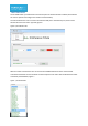
To change the Ethernet setting use the device installer to identify the FS1000 on your network, if the IP address on the reader is on a different subnet to the host PC then the host PC’s subnet must be changed to match that of the readers. With the reader and the host both on the same subnet, the Ethernet settings can be viewed through the web browser, figure 5.
Test Harness The FS-1000 reader is provided with a test harness piece of software written in VB.Net, which allows the user to operate and configure the reader’s full functionality. The harness allows the user to connect via either the USB port or the Ethernet port, these can be selected from the Connection Type tab, figure 6. Figure 6, Connection Tab With the reader connected the user can exercise the FS1000 Commands via the command tab.
With the FS1000 poling rate set, raw tag packets will be shown in the Tag window, figure 8. Figure 8, FS Tag Packets The FS tag messages are formatted as below:2017-08-07 12:23:23;111;2000;5;33;0;8;6;6;3B00;641C;907C;3.0;0;0;0.3;2;0;-66 Figure 9, FS Tag packet Field 1 2 3 4 5 6 7 8 9 10 11 12 13 14 15 16 17 18 19 20 21 Value 2017-08-07 12:23:23 111 2000 5 33 0 8 6 6 3B00 641C 907C 3.0 0 0 0.
To program the tag, a magnet should be placed over the reed switch, after 5 seconds the tag will be programmable. The user sends the program command to the FS1000 and the tag transmits back its new values, figure 14. Figure 14, Tag programming The tags can be programmed at full read range so it is recommended to set an RSSI threshold to reduce the programming range.
Updating FS1000 Firmware The FS1000 Fw can be updated by using the supplied flash tool connected to the header accessible via the panel in the underside of the unit, figure 15. Figure 15, FS1000 Inline programming header Pin1 Pin1 The FS1000 should be connected with Pin1 of the inline programmer connected to Pin1 of the reader. Pin 1 on the programmer is the top most pin of the 6 pin jumper CN4 and is marked with a dot, Pin 1 on the reader is the furthest pin to the right as shown above.
The process to flash the reader straight forward, first open the application, then click file Open and navigate to the Hex file provided. To flash the reader click the program tab, figure 16.
Contact Details Fortecho can be contacted on the details below. Matthew Bignell Systems Engineer Solon House 40A Peterborough Road London SW6 3BN Tel: +44 20 7736 3330 DDI: +44 20 7736 8934 Mob: +44 7425 885 474 Web: www.fortecho.com Fitting Instructions Requirements ▪ FS1000 ▪ Screws Installation First ensure that the mounting surface is clean and free from debris, remove any dirt using the cloth.
End of Life At the end of its functional life the FS1000 must be disposed of in a suitable local recycling facility and in accordance with any local laws pertaining to the recycling of waste electronic equipment. The FS1000 consists of an ABS and Aluminium housing with it are electronic components. It contains no substances banned by the European Union’s Restriction of Hazardous Substances (RoHS) directive. Environmental The FS1000 has an operational temperature range of -20 to +55 Degrees Celsius.