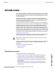
FortiSwitch-5003A and 5003 Fabric and Base Backplane Communications Guide LED MODE 1 0 HOT SWAP 3 2 RESET 5 4 INT FLT 7 6 OK 9 8 EXT FLT 11 10 CLK 13 12 ZRE E1 15 14 Z R E 1 Z R E 0 Z R E 2 E0 SYSTEM CONSOLE R S 2 3 2 E T H O MANAGEMENT FortiSwitch-5003A FortiSwitch-5003 This FortiSwitch-5003A and 5003 Fabric and Base Backplane Communications Guide describes using the FortiSwitch-5003A board and FortiSwitch-5003 board for FortiGate-5000 series base and fabric backplane switching.
Warnings and cautions Only trained and qualified personnel should be allowed to install or maintain FortiGate-5000 series equipment. Read and comply with all warnings, cautions and notices in this document. • • • • • • • • • • ! CAUTION: Risk of Explosion if Battery is replaced by an Incorrect Type. Dispose of Used Batteries According to the Instructions.
Contents Contents Warnings and cautions ..................................................................................... 2 Introduction ........................................................................ 7 About this document......................................................................................... 7 Revision history................................................................................................. 8 FortiSwitch-5003A system .........................................
Contents FortiGate-5050 fabric backplane communication ........ 47 Fabric gigabit switching within a chassis..................................................... 48 Fabric channel connections between FortiSwitch-5003A boards .............. 50 Fabric gigabit switching between chassis.................................................... 50 Fabric gigabit switching to the network........................................................ 52 Fabric 10-gigabit switching within a chassis.............................
Contents config ................................................................................................................ 92 admin user .................................................................................................. 92 route static................................................................................................... 93 switch fabric-channel interface .................................................................... 94 switch fabric-channel physical-port ...........
Contents 6 FortiSwitch-5003A and 5003 Fabric and Base Backplane Communications Guide 01-30000-85717-20081205
Introduction About this document Introduction This FortiSwitch-5003A and 5003 Fabric and Base Backplane Communications Guide contains information, instructions and example configurations for the base and fabric backplane channels and interfaces of FortiGate-5000 ATCA chassis and security systems. FortiGate-5020 chassis is a 2-slot ATCA chassis. The FortiGate-5020 base backplane provides 2 base backplane channels for the base backplane interfaces of FortiGate-5000 boards installed in the chassis.
Revision history Introduction • FortiGate-5140 and 5050 base backplane communication describes supported configurations and features for FortiGate-5140 and 5050 chassis base backplane communications. • FortiGate-5020 base backplane communication describes supported configurations and features for FortiGate-5020 chassis backplane communications. • FortiSwitch-5003A CLI reference describes the FortiSwitch-5003A CLI commands.
FortiSwitch-5003A system FortiSwitch-5003A system The FortiSwitch-5003A board provides 10/1-gigabit fabric backplane channel layer-2 switching and 1-gigabit base backplane channel layer-2 switching in a dual star architecture for the FortiGate-5140 and FortiGate-5050 chassis. The FortiSwitch-5003A board provides a total capacity of 200 Gigabits per second (Gbps) throughput. The FortiGate-5140 chassis is a 14-slot ATCA chassis and the FortiGate-5050 chassis is a 5-slot ATCA chassis.
Front panel LEDs and connectors FortiSwitch-5003A system Figure 1: FortiSwitch-5003A front panel Base Network Activity LEDs RJ-45 COM Port Fabric Network Activity LEDs B1 B2 Base 1G Copper 14/F8 F7 F6 F5 F4 F3 F2 F1 Fabric 10G Optical or Copper SFP Retention Screw OOS Healthy Fault Extraction LED LED LED Lever Reset MGMT 1G Active Switch Copper LED Interface BASE 10G Optical or Copper SFP Retention Screw Hot Swap Extraction LED Lever • One front panel base backplane 10-gigabit optical or copper SF
FortiSwitch-5003A system Front panel LEDs and connectors LEDs Table 2 lists and describes the FortiSwitch-5003A front panel LEDs. Table 2: FortiSwitch-5003A front panel LEDs and switches LED State OOS (Out of Service) Off Normal operation. Red Out of service. The LED turns on if the FortiSwitch-5003A board fails. The LED may also flash briefly when the board is powering on. Green The FortiSwitch-5003A board is powered on and operating normally. Yellow Caution status.
Front panel LEDs and connectors FortiSwitch-5003A system Table 2: FortiSwitch-5003A front panel LEDs and switches (Continued) LED BASE 10G, 14/F8, F7, F6, F5, F4, F3, F2, F1 (Base and Fabric 10 gigabit LEDs) HS (Hot Swap) State Description Solid Green Indicates this interface is connected to a 10-gigabit network device with the correct cable and the attached network device has power. Blinking Green Indicates 10-gigabit network traffic on this interface. Off No link.
FortiSwitch-5003A system Front panel LEDs and connectors Table 3: Base channel interfaces and network activity LEDs Interface Name Description B1 and B2 Front panel gigabit base channel interfaces B1 and B2. Use these interfaces to connect your network to the base channel, to connect base channel 1 to base channel 2, or to connect a base channel on one chassis to a base channel on another chassis. BASE 10G Front panel 10-gigabit base channel interface.
FortiSwitch-5003A configurations FortiSwitch-5003A system Table 5: Fabric network activity LEDs Fabric network activity LED Interface or connection 2/1 Fabric channel connection between fabric channel 1 and fabric channel 2. This LED is lit if there are two FortiSwitch-5003A boards installed in the chassis to indicate fabric backplane communication between them. 3 to 13 Fabric backplane connection to FortiGate-5000 boards in chassis slots 3 to 13.
FortiSwitch-5003A system FortiSwitch-5003A configurations Figure 4: FortiSwitch-5003A base channel 1 HA heartbeat communication 5 4 3 Base channel 1 HA Heartbeat Communication 2 POWER Hot Swap ETH0 Service 5000SM 10/100 link/Act 10/100 link/Act STATUS SERIAL 2 RESET SERIAL 1 ETH0 ETH1 ALARM 5050SAP Hot Swap ETH0 Service ETH0 ETH1 2 STATUS 5000SM 10/100 link/Act 10/100 link/Act SMC RESET 1 SMC 1 Fabric 10-gigabit switching within a chassis One FortiGate-RTM-XB2 provides 10-gigabit
FortiSwitch-5003A configurations FortiSwitch-5003A system Layer-2 link aggregation and redundancy configurations The FortiSwitch-5003A board supports 802.3ad static mode layer-2 link aggregation, 802.1q VLANs, and 802.1s Multi-Spanning Tree Protocol (MSTP) for the fabric channels. You can use these features to configure link aggregation and support redundant FortiSwitch-5003A configurations to distribute traffic to multiple FortiGate-5001A or 5005FA2 boards.
FortiSwitch-5003 system Front panel LEDs and connectors FortiSwitch-5003 system The FortiSwitch-5003 board provides base backplane interface switching for the FortiGate-5140 chassis and the FortiGate-5050 chassis. You can use this switching for data communication or HA heartbeat communication between the base backplane interfaces of FortiGate-5000 series boards installed in slots 3 and up in these chassis.
Front panel LEDs and connectors FortiSwitch-5003 system Figure 7: FortiSwitch-5003 front panel Power LED Hot Swap LED 1 2 0 LED MODE 3 4 RESET 5 6 INT FLT 7 8 OK 9 10 EXT FLT 11 12 CLK 13 14 ZRE E1 15 E0 Z R E 2 Z R E 1 Z R E 0 R S 2 3 2 SYSTEM CONSOLE Extraction ZRE0 ZRE1 ZRE2 Lever Out of base backplane interfaces Service LED Mounting 10/100/1000Base-T Knot Ethernet HOT SWAP ZRE Network LED Mode Switch Activity LEDs Reset (ZRE 0 to 15) Switch CONSOLE RJ-45 Serial E T
FortiSwitch-5003 system Front panel LEDs and connectors Table 7: FortiSwitch-5003 board front panel LEDs and switches (Continued) LED State Description EXT FLT Off Normal operation. Yellow Cannot establish a link to a configured interface or another connection problem external to the FortiSwitch-5003 board. This LED may indicate issues that do not affect normal operation. Off Normal operation. Yellow Failure of internal tests.
Base backplane communications FortiSwitch-5003 system Connectors Table 9 lists and describes the FortiSwitch-5003 front panel connectors. Table 9: FortiSwitch-5003 connectors Connector Type ETH0 Speed RJ-45 100Base-T CONSOLE RJ-45 9600 bps ZRE0, ZRE1, ZRE2 Protocol Description Ethernet Front panel out of band management interface. A second out of band management interface, ETH1, connects to the shelf managers. Neither of the out of band management interfaces are used.
FortiSwitch-5003 system Base backplane communications In a single chassis, more than one cluster can use the same base backplane interface for HA heartbeat communication. To separate heartbeat communication for multiple clusters on the same base backplane interface, configure a different HA group name and password for each cluster. In a single chassis, you can also use the same base backplane interface for data and HA heartbeat communication.
Base backplane communications 22 FortiSwitch-5003 system FortiSwitch-5003A and 5003 Fabric and Base Backplane Communications Guide 01-30000-85717-20081205
FortiGate-5140 fabric backplane communication FortiGate-5140 fabric backplane communication The FortiGate-5140 chassis has two fabric backplane Ethernet channels that can operate at 1 Gbps or 10 Gbps. Available connections to these channels vary by chassis hub/switch slot number. • Hub/switch slot 1 can connect to the first fabric backplane channel (channel 1), and thereby all other chassis slots, except hub/switch slot 2.
Fabric gigabit switching within a chassis FortiGate-5140 fabric backplane communication This section describes: • Fabric gigabit switching within a chassis • Fabric channel connections between FortiSwitch-5003A boards • Fabric gigabit switching between chassis • Fabric gigabit switching to the network • Fabric 10-gigabit switching within a chassis • Fabric channel layer-2 link aggregation • Fabric channel layer-2 link aggregation and redundancy • Example active-passive redundant link config
FortiGate-5140 fabric backplane communication Fabric gigabit switching within a chassis The chassis can be connected to the network using any of the FortiGate-5001A front panel interfaces. You can also connect FortiSwitch-5003A front panel fabric interfaces to the network. You can also install FortiGate AMC modules in the FortiGate-5001A boards and connect the network to the AMC front panel interfaces. The AMC modules and the network connections are not shown in Figure 9.
Fabric gigabit switching within a chassis FortiGate-5140 fabric backplane communication Figure 10: FortiGate-5140 fabric channel 1 and 2 data communication Fabric channel 2 data communication 5140SAP 5140 13 11 9 7 5 3 1 ET RES 2 SERIAL 1 SERIAL 2 ALARM R AL R R2 R3 R1 ITIC MAJO MINO USE USE USE CR 4 6 8 10 12 14 FABRIC FABRIC FABRIC FABRIC FABRIC BASE BASE BASE BASE BASE BASE ACT ACT ACT LINK LINK ACT ACT LINK LINK ACT ACT LINK LINK ACT ACT LINK LINK LINK
FortiGate-5140 fabric backplane communication Fabric channel connections between FortiSwitch-5003A boards Fabric channel connections between FortiSwitch-5003A boards When two FortiSwitch-5003A boards are installed in a single chassis their fabric channels are connected together. This means there is a data connection between fabric channel 1 and fabric channel 2. Unless you are going to use this connection you should disable it.
Fabric gigabit switching between chassis FortiGate-5140 fabric backplane communication The chassis can be connected to the network using any of the FortiGate front panel interfaces. You can also connect FortiSwitch-5003A front panel fabric interfaces to the network. You can also install FortiGate AMC modules in the FortiGate-5001A boards and connect networks to the AMC front panel interfaces. The AMC modules and the network connections are not shown in Figure 11.
FortiGate-5140 fabric backplane communication Fabric gigabit switching to the network If the data traffic contains VLAN-tagged packets, you must add the VLAN tags to the FortiSwitch-5003A interfaces that will handle the VLAN-tagged traffic.
Fabric gigabit switching to the network FortiGate-5140 fabric backplane communication Figure 12: Fabric channel 2 connected to an internal network and fabric channel 1 connected to an external network Internal Network Fabric channel 2 data communication Internal network connected to the F7 front panel fabric interface to connect to fabric channel 2 5140SAP 5140 13 11 9 7 5 3 1 T SE RE 2 SERIAL 1 SERIAL 2 ALARM 2 3 1 R AL R ITIC MAJO MINO USER USER USER CR 4 6 8 10 12 14 5000SM 10/10
FortiGate-5140 fabric backplane communication Fabric 10-gigabit switching within a chassis Fabric 10-gigabit switching within a chassis All of the FortiSwitch-5003A fabric front panel interfaces are 10-gigabit interfaces and the FortiSwitch-5003A board supports 10-gigabit communication across the fabric backplane channels. The FortiGate-5001A board also supports 10-gigabit communication on the fabric backplane with the addition of a FortiGate-RTM-XB2 module.
Fabric 10-gigabit switching within a chassis FortiGate-5140 fabric backplane communication Figure 13: Example 10-gigabit connection between internal and external networks Internal Network FortiGate-RTM-XB2 modules installed in RTM slots 6, 8, and 10 provide two 10-gigabit fabric channels and NP2 acceleration for each FortiGate-5001A board Fabric channel 2 10-gigabit data communication Internal 10-gigabit network connected to fabric channel 2 5140SAP 5140 13 11 9 7 5 3 1 T SE RE 2 SERIAL 1 S
FortiGate-5140 fabric backplane communication Fabric channel layer-2 link aggregation Fabric channel layer-2 link aggregation FortiSwitch-5003A boards support 802.3ad static mode layer-2 link aggregation and 802.1q VLANs for the fabric channels. You can use these features to configure link aggregation to distribute traffic to multiple FortiGate-5001A or 5005FA2 boards. Link aggregation configurations also support IPv6 traffic and traffic with jumbo frames up to 16 kbytes.
Fabric channel layer-2 link aggregation FortiGate-5140 fabric backplane communication Because the FortiGate-5000 boards in a link aggregation configuration operate in transparent mode, any routing, VPN or NAT requirements should be handed by an external device (such as a router), before or after the traffic reaches the FortiSwitch-5003A board.
FortiGate-5140 fabric backplane communication Fabric channel layer-2 link aggregation The FortiSwitch-5003A configuration consists of adding a trunk named trunk_6 that aggregates backplane slots 6, 8, 9, 10, 11, and 13: config switch fabric-channel trunk edit "trunk_6" set members "slot-6" "slot-8" "slot-9" "slot-10" "slot-11" "slot-13" end Allow VLAN packets on the FortiSwitch-5003A F7 front panel interface and the trunk: config switch fabric-channel interface edit "f7" set allowed-vlans 1,100-101 next e
Fabric channel layer-2 link aggregation and redundancy FortiGate-5140 fabric backplane communication You must also enable the FortiSwitch-5003A board to listen for heartbeat packets on all of the interfaces connected to FortiGate-5001A boards: config switch fabric-channel physical-port edit "slot-6" set heartbeat enable next edit "slot-8" set heartbeat enable next edit "slot-9" set heartbeat enable next edit "slot-10" set heartbeat enable next edit "slot-11" set heartbeat enable next edit "slot-13" set he
FortiGate-5140 fabric backplane communication Example active-passive redundant link configuration The configuration of the spanning tree instances determines whether you create an active-passive or active-active configuration: • For an active-passive configuration, you can create one spanning tree instance on all three devices and give one of the FortiSwitch-5003A boards a higher priority.
Example active-passive redundant link configuration FortiGate-5140 fabric backplane communication All of the FortiGate-5001A boards must be operating in transparent mode and all must have the same configuration. In this redundant configuration, traffic can be re-directed from one fabric channel to another after a FortiSwitch-5003A fails or if you change the MSTP configuration.
FortiGate-5140 fabric backplane communication Example active-passive redundant link configuration 2 Configure the switch to add VLAN tag 103 and 104 to packets from the internal networks and VLAN tag 105 and 106 to packets from the external networks and to send packets from all of these networks to the FortiSwitch-5003A board.
Example active-passive redundant link configuration 3 FortiGate-5140 fabric backplane communication Add two spanning tree instances numbered the same as the instances added to the switch (3 and 5).
FortiGate-5140 fabric backplane communication Example active-passive redundant link configuration Verifying the MSTP configuration of the FortiSwitch-5003A board in slot 1 Enter diagnose spanning-tree mst-config fabric-channel to display the FortiSwitch-5003A fabric channel MSTP configuration.
Example active-passive redundant link configuration FortiGate-5140 fabric backplane communication Example configuration for the FortiSwitch-5003A board in slot 2 The FortiSwitch-5003A board in slot 2 requires the same configuration settings as the FortiSwitch-5003A board in slot 1 except that the priority values of both spanning tree instances is set higher for the FortiSwitch-5003A board in slot 2: config switch fabric-channel stp instance edit 3 set priority 40960 set vlan-range 103-104 next edit 5 set
FortiGate-5140 fabric backplane communication Example active-passive redundant link configuration Example FortiGate-5001A configuration All of the FortiGate-5001A boards must be operating in transparent mode and all must have the same configuration. The spanning tree instances can send traffic to fabric channel 1 or fabric channel 2. As a result, traffic can enter and exit the FortiGate-5001A boards using the fabric1 interface or the fabric2 interface.
Example active-active redundant link configuration FortiGate-5140 fabric backplane communication edit vlan_fab2_105 set interface fabric2 set vlanid 105 set vdom root etc... next edit vlan_fab2_106 set interface fabric2 set vlanid 106 set vdom root etc... end You should also configure the FortiGate-5001A boards to send heartbeat packets over the fabric1 and fabric2 channels so that the FortiSwitch-5003A board can verify that the FortiGate-5001A boards are functioning.
FortiGate-5140 fabric backplane communication Example active-active redundant link configuration edit 5 set priority 4096 set vlan-range 105-106 end Verifying the spanning tree configuration of the FortiSwitch-5003A board in slot 1 To display the configuration of spanning tree instance 3 for the FortiSwitch-5003A F7 interface enter: diagnose spanning-tree instance fabric-channel 3 f7 MST Instance Information, Fabric-Channel: Instance ID : 3 Mapped VLANs : 103 104 Switch Priority : 4096 Regional Root MAC
Example active-active redundant link configuration 46 FortiGate-5140 fabric backplane communication FortiSwitch-5003A and 5003 Fabric and Base Backplane Communications Guide 01-30000-85717-20081205
FortiGate-5050 fabric backplane communication FortiGate-5050 fabric backplane communication The FortiGate-5505 chassis has two fabric backplane Ethernet channels that can operate at 1 Gbps or 10 Gbps. Available connections to these channels vary by hub/switch slot number. • Hub/switch slot 1 can connect to the first fabric backplane channel (channel 1), and thereby all other chassis slots, except hub/switch slot 2.
Fabric gigabit switching within a chassis FortiGate-5050 fabric backplane communication This section describes: • Fabric gigabit switching within a chassis • Fabric channel connections between FortiSwitch-5003A boards • Fabric gigabit switching between chassis • Fabric gigabit switching to the network • Fabric 10-gigabit switching within a chassis • Fabric channel layer-2 link aggregation • Fabric channel layer-2 link aggregation and redundancy • Example active-passive redundant link config
FortiGate-5050 fabric backplane communication Fabric gigabit switching within a chassis For the FortiGate-5001A boards to use the fabric channel 2 for data communication you must show backplane interfaces on the FortiGate-5001A web-based manager and then configure firewall polices and routing for the fabric2 interfaces. If the data traffic contains VLAN-tagged packets, you must add the VLAN tags to the FortiSwitch-5003A interfaces that will handle the VLAN-tagged traffic.
Fabric channel connections between FortiSwitch-5003A boards FortiGate-5050 fabric backplane communication If the data traffic contains VLAN-tagged packets, you must add the VLAN tags to the FortiSwitch-5003A interfaces that will handle the VLAN-tagged traffic.
FortiGate-5050 fabric backplane communication Fabric gigabit switching between chassis Figure 18 shows data communication between two FortiGate-5050 chassis using fabric channel 2. The top chassis in the figure contains a FortiSwitch-5003A board in hub/switch slot 2 and three FortiGate-5001A boards. The bottom chassis contains a FortiSwitch-5003A board also in hub/switch slot 2 and two FortiGate-5005FA2 boards.
Fabric gigabit switching to the network FortiGate-5050 fabric backplane communication If the data traffic contains VLAN-tagged packets, you must add the VLAN tags to the FortiSwitch-5003A interfaces that will handle the VLAN-tagged traffic.
FortiGate-5050 fabric backplane communication Fabric gigabit switching to the network Figure 19: Fabric channel 2 connected to an internal network and fabric channel 1 connected to an external network Internal Network Internal network connected to the F7 front panel fabric interface to connect to fabric channel 2 5 Fabric channel 1 Data Communication 4 Fabric channel 2 Data Communication 3 2 POWER Hot Swap ETH0 Service STATUS 5000SM 10/100 link/Act 10/100 link/Act RESET SERIAL 2 ETH0 ETH1 5
Fabric 10-gigabit switching within a chassis FortiGate-5050 fabric backplane communication Fabric 10-gigabit switching within a chassis All of the FortiSwitch-5003A fabric front panel interfaces are 10-gigabit interfaces and the FortiSwitch-5003A board supports 10-gigabit communication across the fabric backplane channels. The FortiGate-5001A board also supports 10-gigabit communication on the fabric backplane with the addition of a FortiGate-RTM-XB2 module.
FortiGate-5050 fabric backplane communication Fabric 10-gigabit switching within a chassis Figure 20: Example 10-gigabit connection between internal and external networks FortiGate-RTM-XB2 module installed in RTM slot 3 provides two 10-gigabit fabric channels and NP2 acceleration for the FortiGate-5001A board Internal Network Internal 10-gigabit Network Connected to Fabric Channel 2 FortiGate-5001A Board Installed in FortiGate-5050 front panel slot 3 5 4 3 Fabric Channel 1 10 Gigabit Data Communicati
Fabric channel layer-2 link aggregation FortiGate-5050 fabric backplane communication Fabric channel layer-2 link aggregation FortiSwitch-5003A boards support 802.3ad static mode layer-2 link aggregation and 802.1q VLANs for the fabric channels. You can use these features to configure link aggregation to distribute traffic to multiple FortiGate-5001A or 5005FA2 boards. Link aggregation configurations also support IPv6 traffic and traffic with jumbo frames up to 16 kbytes.
FortiGate-5050 fabric backplane communication Fabric channel layer-2 link aggregation Note: Due to the way the hash algorithm works, FortiGate-5000 boards in the lower numbered chassis slots in a trunk may receive more traffic. The order of the interfaces in the trunk does not matter, the numerically lowest slots will always be the ones to receive more traffic if the number of interfaces in the trunk is not a power of 2.
Fabric channel layer-2 link aggregation FortiGate-5050 fabric backplane communication The FortiSwitch-5003A configuration consists of adding a trunk named trunk_345 that aggregates backplane slots 3, 4, and 5: config switch fabric-channel trunk edit "trunk_345" set members "slot-3" "slot-4" "slot-5" end Allow VLAN packets on the FortiSwitch-5003A F5 front panel interface and the trunk: config switch fabric-channel interface edit "f5" set allowed-vlans 1,100-101 next edit "trunk_345" set allowed-vlans 1,10
FortiGate-5050 fabric backplane communication Fabric channel layer-2 link aggregation and redundancy You must also enable the FortiSwitch-5003A board to listen for heartbeat packets on all of the interfaces connected to FortiGate-5001A boards: config switch fabric-channel physical-port edit "slot-3" set heartbeat enable next edit "slot-4" set heartbeat enable next edit "slot-5" set heartbeat enable end Fabric channel layer-2 link aggregation and redundancy In addition to 802.
Example active-passive redundant link configuration • FortiGate-5050 fabric backplane communication For an active-active configuration, you create two or more spanning tree instances on all three devices and give some instances a higher priority on one FortiSwitch-5003A board and give other instances a higher on the other FortiSwitch-5003A board. While both FortiSwitch-5003A boards are operating, the spanning tree configuration distributes traffic to both boards.
FortiGate-5050 fabric backplane communication Example active-passive redundant link configuration Figure 22: Redundant link aggregation configuration Internal Network External Network Internal and external 10-gigabit networks connected to FortiSwitch-5003A front panel interface F5 and to fabric channels 1 and 2 External switch VLAN tagged traffic Three FortiGate-RTM-XB2 modules installed in RTM slots 3, 4, and 5 to provide 10-gigabit fabric interfaces and NP2 acceleration for each FortiGate-5001A board
Example active-passive redundant link configuration 4 FortiGate-5050 fabric backplane communication Add spanning tree instance 5 for packets from the external networks. Add VLAN tags 101 to this spanning tree instance. Set the priority of this spanning tree instance to 5, the same as instance 3.
FortiGate-5050 fabric backplane communication 6 Example active-passive redundant link configuration Enable the FortiSwitch-5003A board to listen for heartbeat packets on the interfaces connected to FortiGate-5001A boards: config switch fabric-channel physical-port edit "slot-3" set heartbeat enable next edit "slot-4" set heartbeat enable next edit "slot-5" set heartbeat enable end Verifying the MSTP tree configuration of the FortiSwitch-5003A board in slot 1 Enter diagnose spanning-tree mst-config fabri
Example active-passive redundant link configuration FortiGate-5050 fabric backplane communication Example configuration for the FortiSwitch-5003A board in slot 2 The FortiSwitch-5003A board in slot 2 requires the same configuration settings as the FortiSwitch-5003A board in slot 1 except that the priority values of both spanning tree instances are set higher for the FortiSwitch-5003A board in slot 2: config switch fabric-channel stp instance edit 3 set priority 40960 set vlan-range 100 next edit 5 set pri
FortiGate-5050 fabric backplane communication Example active-passive redundant link configuration Example FortiGate-5001A configuration All of the FortiGate-5001A boards must be operating in transparent mode and all must have the same configuration. The spanning tree instances can send traffic to fabric channel 1 or fabric channel 2. As a result, traffic can enter and exit the FortiGate-5001A boards using the fabric1 interface or the fabric2 interface.
Example active-active redundant link configuration FortiGate-5050 fabric backplane communication Example active-active redundant link configuration You can make the previous example an active-active redundant link configuration that sends all traffic from the internal network to one FortiSwitch-5003A board and all traffic from the external network to the other FortiSwitch-5003A board by changing the priorities of the spanning tree instances added to the FortiSwitch-5003A boards.
FortiGate-5140 and 5050 base backplane communication FortiGate-5140 and 5050 base backplane communication The FortiGate-5140 chassis and the FortiGate-5050 chassis have two base backplane Ethernet channels. Available connections to these channels vary by hub/switch slot number. • Hub/switch slot 1 can connect to the first base backplane channel, and thereby all other chassis slots, except hub/switch slot 2.
Base channel connections between FortiSwitch-5003A boards FortiGate-5140 and 5050 base backplane communication This section contains example base channel HA and network configurations for each hardware combination. It also discusses how to choose an appropriate amount and slot number of FortiSwitch boards for base backplane HA.
FortiGate-5140 and 5050 base backplane communication Base backplane HA configurations It makes no difference which FortiSwitch-5003A base front panel interfaces you use to link the base channels. You can connect an Ethernet cable, either straightthrough or crossover, from any base front panel interface on one FortiSwitch-5003A board to any base front panel interface on another FortiSwitch-5003A board installed in the other chassis.
Base backplane HA configurations FortiGate-5140 and 5050 base backplane communication • Separate multiple sensitive or high volume communications, such as HA communications for multiple clusters. For example, if you have two busy FortiGate-5005FA2 clusters, you might configure one cluster to use base1 for HA heartbeat traffic and the other to use base2. Note: More than one cluster can use the same base backplane channel for HA communication.
FortiGate-5140 and 5050 base backplane communication Base backplane HA configurations Figure 26: FortiGate-5140 inter-chassis HA cluster using both base backplane heartbeat interfaces (through FortiSwitch-5003A boards in hub/switch slots 1 and 2) Internal Network External switch 5140SAP 5140 13 11 9 7 5 3 1 T SE RE 2 SERIAL 1 SERIAL 2 ALARM 6 8 10 12 5140SAP 5140 2 1 3 R AL ITIC MAJO MINOR USER USER USER CR 4 14 13 11 9 7 5 3 1 T SE RE 2 SERIAL 1 SERIAL 2 ALARM 2 1 3 R
Base backplane HA configurations FortiGate-5140 and 5050 base backplane communication Figure 27: FortiGate-5005FA2 heartbeat failover from hub/switch slot 1 (base1) to hub/switch slot 2 (base2) Figure 28: FortiGate-5001SX/FortiGate-5001FA2 heartbeat failover from hub/switch slot 2 (port10) to hub/switch slot 1 (port9) 72 FortiSwitch-5003A and 5003 Fabric and Base Backplane Communications Guide 01-30000-85717-20081205
FortiGate-5140 and 5050 base backplane communication Base backplane HA configurations To configure HA interface failover to use two FortiSwitch boards 1 Insert the FortiSwitch boards into chassis hub/switch slot 1 and hub/switch slot 2. If you want to form an HA cluster between FortiGate boards in separate chassis, link the base backplanes of each chassis by connecting FortiSwitch boards front panel base or ZRE interfaces with an Ethernet cable.
Base backplane HA configurations FortiGate-5140 and 5050 base backplane communication Note: Using a single FortiSwitch board for HA heartbeat communication introduces a single point of failure. If this FortiSwitch board fails or is removed, HA heartbeat communication will be interrupted. For enhanced reliability, you can add a second FortiSwitch board. You can also improve reliability by connecting and configuring one or more other heartbeat interfaces.
FortiGate-5140 and 5050 base backplane communication Base backplane HA configurations To configure your HA cluster to use the base backplane interface connected through a single FortiSwitch, the base backplane interface must be enabled as a heartbeat interface and: • if priorities are not equal, have the highest priority of all heartbeat interfaces • if priorities are equal, be the first interface on the indexed heartbeat interface list You can satisfy these requirements in multiple ways by adjusting
Base backplane HA configurations FortiGate-5140 and 5050 base backplane communication Figure 32: FortiGate-5001SX/FortiGate-5001FA2 HA through slot 2 (port10) with failover to a non-base backplane interface (port8) To configure HA communications to use one FortiSwitch board 1 Insert the FortiSwitch board into chassis hub/switch slot 1 or hub/switch slot 2. When installing only one FortiSwitch board per chassis, recommended slot number varies by the model of the FortiGate boards.
FortiGate-5140 and 5050 base backplane communication 8 Base backplane HA configurations • If interface priorities are not all equal, set the base backplane interface priority to a higher value than all other interfaces. • If interface priorities are all equal, set the base backplane interface priority to a higher value than all other interfaces, or disable interfaces listed above the base backplane interface in the Heartbeat Interface list.
Base backplane HA configurations FortiGate-5140 and 5050 base backplane communication This list is sorted into hash map order, rather than purely by alphabetical order or purely by interface number value comparisons. As a result, the list is sorted primarily alphabetical by interface name (for example, base1 is before port1), then secondarily by index numbers: • 1 • 10 • 2 through 8 • 9 Note: For FortiOS versions 3.
FortiGate-5140 and 5050 base backplane communication Base backplane data configurations Base backplane data configurations In addition to HA traffic, FortiSwitch boards can pass other traffic types through or to the base backplane. Note: FortiSwitch-5003 boards do not support VLAN-tagged packets, so if you are using the FortiSwitch-5003 board base backplane traffic cannot include VLAN-tagged packets. FortiSwitch-5003A boards do support VLAN-tagged packets over the base channels.
Base backplane data configurations FortiGate-5140 and 5050 base backplane communication Connecting FortiGate boards to the network By installing one or two FortiSwitch boards per chassis, you can connect FortiGate boards to the network or Internet through their base backplane interfaces. There are several ways you can connect FortiGate boards to the network, depending on your available hardware and other goals such as hardware redundancy.
FortiGate-5020 base backplane communication HA configurations FortiGate-5020 base backplane communication The FortiGate-5020 chassis has two base backplane Ethernet channels. FortiGate modules installed in each slot can directly connect to the other slot through either channel. Because of the base backplane’s topology, connecting FortiGate modules to each other through the base backplane does not require any additional hardware (that is, FortiSwitch modules are not required).
HA configurations FortiGate-5020 base backplane communication Heartbeat failover between channels To configure your HA cluster with a heartbeat that fails over between the two base backplane interfaces, both base backplane interfaces must be enabled and: • if priorities are not equal, must have the highest priorities of all heartbeat interfaces • if priorities are equal, be the first interfaces on the indexed Heartbeat Interface list If you also want to specify which base backplane channel is used as
FortiGate-5020 base backplane communication HA configurations Figure 34: FortiGate-5005FA2 heartbeat failover between base backplane channels Figure 35: FortiGate-5001SX/FortiGate-5001FA2 heartbeat failover between base backplane channels To configure heartbeat interface failover between two base backplane channels 1 Insert FortiGate modules into the chassis slots. For details on hardware installation and related warnings and cautions, see the FortiGate-5000 Series Introduction.
Inter-chassis HA configurations FortiGate-5020 base backplane communication 3 On each FortiGate module to be included in the HA cluster, go to System > Config > HA. 4 Select the Mode, then enter the Group Name, and Password. You may also want to set other options, such as the Device Priority or session pick-up. For detailed instructions, see the FortiGate HA Guide.
FortiGate-5020 base backplane communication Inter-chassis HA configurations Figure 36: FortiGate-5020 inter-chassis network and heartbeat connections Internal Network internal network switch inter-chassis heartbeat switch CONSOLE USB 1 2 3 4 5 6 7 8 CONSOLE USB 1 2 3 4 5 6 7 8 PSU A PSU A PSU B PSU B STA IPM PWR ACC STA IPM PWR ACC CONSOLE USB 1 2 3 4 5 6 7 8 CONSOLE USB 1 2 3 4 5 6 7 8 STA IPM PWR ACC PWR ACC STA IPM switch inter-chassis heartbeat swi
Network configurations FortiGate-5020 base backplane communication Network configurations In addition to HA traffic, the FortiGate-5020chassis base backplane can pass other traffic types, including VLAN tagged network traffic. FortiGate modules do not necessarily have to be the same model.
FortiGate-5020 base backplane communication Network configurations Figure 39: Network connection between two modules in the same chassis PSU A PSU B base backplane channel 1 CONSOLE USB 1 2 3 4 5 6 7 8 CONSOLE USB 1 2 3 4 5 6 7 8 STA IPM PWR ACC PWR ACC FortiSwitch-5003A and 5003 Fabric and Base Backplane Communications Guide 01-30000-85717-20081205 STA IPM base backplane channel 2 87
Network configurations 88 FortiGate-5020 base backplane communication FortiSwitch-5003A and 5003 Fabric and Base Backplane Communications Guide 01-30000-85717-20081205
FortiSwitch-5003A CLI reference Connecting to the CLI FortiSwitch-5003A CLI reference This chapter describes the FortiSwitch-5003A CLI config, execute, and get commands and some diagnose commands. This chapter also describes how to connect to the FortiSwitch-5003A CLI. Working with the FortiSwitch-5003A CLI is the same as working with the FortiOS CLI. For information about CLI command syntax, CLI objects and other CLI basics see the FortiGate CLI Reference.
Connecting to the CLI 6 FortiSwitch-5003A CLI reference Select the following port settings and select OK. Bits per second 9600 7 Data bits 8 Parity None Stop bits 1 Flow control None Press Enter to connect to the FortiSwitch-5003A CLI. A prompt similar to the following appears. FS5A033E08000111 login: The prompt includes the FortiSwitch-5003A host name. The default host name is the FortiSwitch-5003A serial number. 8 Type a valid administrator name and press Enter.
FortiSwitch-5003A CLI reference Connecting to the CLI Connecting to the FortiSwitch-5003A CLI using SSH Secure Shell (SSH) provides strong secure authentication and secure communications to the FortiSwitch-5003A CLI from your internal network or the internet. Once the FortiSwitch-5003A board is configured to accept SSH connections, you can run an SSH client on your management computer and use this client to connect to the FortiSwitch-5003A CLI.
config FortiSwitch-5003A CLI reference config The following config commands are available: • admin user • route static • switch fabric-channel interface • switch fabric-channel physical-port • switch fabric-channel stp instance • switch fabric-channel stp settings • switch fabric-channel trunk • system global • system interface admin user Use this command to add and configure FortiSwitch-5003A administrator accounts.
FortiSwitch-5003A CLI reference config route static Use this command to add, edit, or delete static routes for the mgmt interface. Syntax config route static edit set device set dst set gateway end Variables Description Default edit Enter a sequence number to identify the static route. No default.
config FortiSwitch-5003A CLI reference switch fabric-channel interface Use this command to configure the VLANs allowed on FortiSwitch-5003A fabric channel interfaces. You can also change the native VLAN for each interface and disable or enable MSTP for each interface.
FortiSwitch-5003A CLI reference config Example This example shows how to allow VLAN tags 201 to 210 on slots 6, 8, and 10 and the F1 front panel interface.
config FortiSwitch-5003A CLI reference switch fabric-channel physical-port Use this command to change the administrative status of FortiSwitch-5003A fabric channel interfaces (bring each interface up or down) and configure each fabric channel interface to receive heartbeat packets from FortiGate-5001A or 5005FA2 fabric channel interfaces.
FortiSwitch-5003A CLI reference config Examples This example shows how to enable the FortiSwitch-5003A board to listen for heartbeat packets on the interfaces for chassis slots 6, 8, and 10: config switch fabric-channel physical-port edit "slot-6" set heartbeat enable next edit "slot-8" set heartbeat enable next edit "slot-10" set heartbeat enable end This example shows how to bring down the slot-2/1 FortiSwitch-5003A interface.
config FortiSwitch-5003A CLI reference switch fabric-channel stp instance Use this command to add and configure 802.1s Multi-Spanning Tree Protocol (MSTP) spanning tree instances. A spanning tree instance consists of the following: • An instance ID • A priority value • A VLAN range • A cost and priority value for each FortiSwitch-5003A interface (configured with the config stp-port command).
FortiSwitch-5003A CLI reference config config stp-port Use this command to change the spanning tree cost and priority for each FortiSwitch-5003A interface in a spanning tree instance. When you add a new spanning tree instance the cost of each interface in the spanning tree instance is set to 0 and the priority is set to 128.
config FortiSwitch-5003A CLI reference switch fabric-channel stp settings Use this command to change MSTP spanning tree timers, specify an MSTP region name and use a revision number to track changes to the MSTP configuration. All of these MSTP settings should be the same on all of the devices in an MSTP region. These settings apply to all MSTP instances added to a FortiSwitch-5003A board.
FortiSwitch-5003A CLI reference config switch fabric-channel trunk Use this command to create a trunk and add FortiSwitch-5003A interfaces to the trunk. You use trunks to group FortiSwitch-5003A interfaces so that you can use 802.3ad static mode layer-2 link aggregation to distribute sessions to the fabric interfaces of the FortiGate-5001A and 5005FA2 boards connected to the FortiSwitch-5003A interfaces in the trunk.
config FortiSwitch-5003A CLI reference Related topics 102 • config switch fabric-channel interface • config switch fabric-channel physical-port • config switch fabric-channel stp instance • config switch fabric-channel stp settings FortiSwitch-5003A and 5003 Fabric and Base Backplane Communications Guide 01-30000-85717-20081205
FortiSwitch-5003A CLI reference config system global Use this command to enable daylight saving time and configure the hostname and time zone for a FortiSwitch-5003A board. Syntax config system global set daylightsavetime {disable | enable} set hostname set timezone end Variables Description Default daylightsavetime {disable Enable or disable daylight saving time.
config FortiSwitch-5003A CLI reference system interface Use this command to change the IP address and management access setting of the FortiSwitch-5003A mgmt (management) interface and to bring the mgmt interface up or down. Syntax config system interface set status {down | up} set ip set allowaccess end Variables Description Default status {down | up} Bring the mgmt interface up or down (start or stop the interface).
FortiSwitch-5003A CLI reference execute execute The following execute commands are available: • backup • bootimage • date • factory-reset • ping • reboot • restore • shutdown • time • top • traceroute backup Back up the FortiSwitch-5003A configuration to a TFTP server.
execute FortiSwitch-5003A CLI reference bootimage Use this command to change the firmware image used to start the FortiSwitch-5003A board by switching between the primary or secondary firmware image. To use this command you must install a primary and a secondary firmware image by using the system startup options available when you reboot the FortiSwitch-5003A from a console connection to the FortiSwitch-5003A COM port.
FortiSwitch-5003A CLI reference execute date Display or set the system date. Syntax execute date [] date_str has the form mm/dd/yyyy, where • • • mm is the month and can be 1 to 12 dd is the day of the month and can be 1 to 31 yyyy is the year and can be from 2001 to 2037 If you do not specify a date, the command returns the current system date. Shortened values for the year, such as ‘06’ instead of ‘2006’ are not valid. Shortened values for the month and year are valid.
execute FortiSwitch-5003A CLI reference factory-reset Reset the FortiSwitch-5003A configuration to factory default settings. Syntax execute factory-reset ! 108 Caution: This command deletes all changes that you have made to the FortiSwitch-5003A configuration and reverts the system to its original configuration, including resetting the mgmt interface IP address.
FortiSwitch-5003A CLI reference execute ping Send an ICMP echo request (ping) to test the network connection between the FortiSwitch-5003A mgmt interface and another network device. You must add a DNS server to the FortiSwitch-5003A configuration to ping a hostname. Syntax execute ping { | } should be a fully qualified domain name, for example: www.fortinet.com. Example This example shows how to ping a host with the IP address 172.20.120.11. execute ping 172.
execute FortiSwitch-5003A CLI reference reboot Restart the FortiSwitch-5003A board. While the FortiSwitch-5003A board is rebooting it cannot forward traffic.
FortiSwitch-5003A CLI reference execute restore Use this command to restore the FortiSwitch-5003A configuration from a file on a TFTP server or change the FortiSwitch-5003A firmware. Syntax execute restore config execute restore config execute restore image tftp Variables Description config Restore the system configuration from a file on a TFTP server. The new configuration replaces the existing configuration.
execute FortiSwitch-5003A CLI reference shutdown Shut down the FortiSwitch-5003A board now. You will be prompted to confirm the shutdown.
FortiSwitch-5003A CLI reference execute time Get or set the system time. Syntax execute time [] time_str has the form hh:mm:ss, where • • • hh is the hour and can be 00 to 23 mm is the minutes and can be 00 to 59 ss is the seconds and can be 00 to 59 If you do not specify a time, the command returns the current system time. You are allowed to shorten numbers to only one digit when setting the time. For example both 01:01:01 and 1:1:1 are allowed.
execute FortiSwitch-5003A CLI reference top Display a list of processes running on the FortiSwitch-5003A board. The command also displays information about each process. Mem: 100168K used, 406696K free, 0K shrd, 344K buff, 75092K cached CPU: 0% usr 0% sys 0% nice 100% idle 0% io 0% irq 0% softirq Load average: 0.00 0.00 0.00 PID PPID USER STAT VSZ %MEM %CPU COMMAND 79 49 root S 4276 1% 0% -newcli admin --userfrom=telnet(172.
FortiSwitch-5003A CLI reference execute traceroute Test the connection between the FortiSwitch-5003A board and an address or hostname and display information about the network hops between the address and the FortiSwitch-5003A board. You must add a DNS server to the FortiSwitch-5003A configuration to trace the rout to a hostname. Syntax execute traceroute { | } Example This example shows how to test the connection with 172.20.120.178.
get FortiSwitch-5003A CLI reference get The following get commands are available: • system performance • system status system performance Use this command to display FortiSwitch-5003A CPU usage, memory usage, and USB disk usage. Syntax get system performance Example The output looks like this (for an idle system): # get system performance CPU: Used: 2.9% Total: 506,864 KB Used: 25,228 KB Memory: 5.0% USB Disk: 116 Total: 27,265 KB Used: 9,733 KB 35.
FortiSwitch-5003A CLI reference get system status Use this command to display FortiSwitch-5003A system status information including: • firmware version, build number and branch point • serial number • host name • system time and date and related settings Syntax get system status Example output Version: FortiSwitch-5003A 3.
diagnose FortiSwitch-5003A CLI reference diagnose This section describes some of the available FortiSwitch-5003A diagnose commands. You can use diagnose commands for debugging the operation of the FortiSwitch-5003A board and to set parameters for displaying different levels of diagnostic information. ! Caution: Diagnose commands are intended for advanced users only. Contact Fortinet technical support before using these commands.
FortiSwitch-5003A CLI reference diagnose spanning-tree instance fabric-channel Display the configuration of a spanning tree instance for an interface. For example, to display the configuration of spanning tree instance 5 for the FortiSwitch-5003A F5 interface enter: Syntax diagnose spanning-tree instance fabric-channel [] Variables Description The number of a spanning tree instance added to the FortiSwitch-5003A board in the range 0 to 15.
diagnose FortiSwitch-5003A CLI reference spanning-tree mst-config fabric-channel Display the FortiSwitch-5003A fabric channel MSTP configuration.
FortiSwitch-5003A CLI reference diagnose switch fabric-channel mac-address filter Filter the FortiSwitch-5003A MAC addresses.
diagnose FortiSwitch-5003A CLI reference switch fabric-channel mac-address list Verify the FortiSwitch-5003A MAC address table.
Index Index Numerics 802.1q VLANs 33, 36, 56, 59 802.1s Multi-Spanning Tree Protocol 36, 59, 98 802.3ad dynamic mode layer-2 link aggregation 8, 33, 56 802.
Index fabric channel 1 24 channel 1 and 2 26, 49 channel 2 48 connection between FortiSwitch-5003A boards 27, 50 gigabit switching between chassis 27, 50 gigabit switching to the network 29, 52 gigabit switching within a chassis 24, 48 fabric backplane 82 fabric backplane channel 23, 47 fabric channel disabling communication between 97 heartbeat 96 layer-2 link aggregation 33, 36, 56, 59 MSTP 33, 36, 56, 59, 98 redundancy 33, 36, 56, 59 spanning tree 33, 36, 56, 59 fabric channel interface VLANs allowed 94
Index hops maximum 100 MSTP max-hops 100 hostname FortiSwitch-5003A 103 hub/switch slots 24, 48 hub/switch slot 1 23, 47, 67, 72, 73, 76, 77, 79 hub/switch slot 2 23, 47, 67, 68, 72, 73, 76, 77, 79 hub/switch slot number 23, 47, 67 hub/switch slots 25, 49 I IEEE 802.
Index synchronization 73 system global CLI command 103 system interface CLI command 104 system performance CLI command 116 system status CLI command 117 restore CLI command 111 revision 100 MSTP revision number 100 robustness 77 route static CLI command 93 S show backplane interfaces 25, 28, 30, 49, 51, 53 shutdown CLI command 112 single point of failure 74, 77 slot hub/switch 24, 48 slot 1 23, 47, 67, 75, 78, 86 slot 2 23, 47, 67, 76, 78, 86 slot number 68, 73, 76, 77, 78, 79 slots hub/switch 25, 49 spa
For more information Fortinet documentation For more information Support for your Fortinet product is available as online help from within the web-based manager, from the Tools and Documentation CD included with the product, on the Fortinet Technical Documentation web site, from the Fortinet Knowledge Center web site, as well as from Fortinet Technical Support.
© Copyright 2008 Fortinet, Inc. All rights reserved. No part of this publication including text, examples, diagrams or illustrations may be reproduced, transmitted, or translated in any form or by any means, electronic, mechanical, manual, optical or otherwise, for any purpose, without prior written permission of Fortinet, Inc.