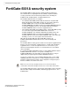
FortiGate-5001A Security System Guide FortiGate-5001A-DW 5001A-SW FortiGate-5001A-SW A detailed guide to the FortiGate-5001A-DW and FortiGate-5001A-SW Security Systems. This FortiGate-5001A Security System Guide describes FortiGate-5001A hardware features, how to install a FortiGate-5001A board in a FortiGate-5000 series chassis, and how to configure the FortiGate-5001A security system for your network.
Warnings and cautions Only trained and qualified personnel should be allowed to install or maintain FortiGate-5000 series equipment. Read and comply with all warnings, cautions and notices in this document. • • • • • • • • • • ! CAUTION: Risk of Explosion if Battery is replaced by an Incorrect Type. Dispose of Used Batteries According to the Instructions.
Contents Contents Warnings and cautions ..................................................................................... 2 FortiGate-5001A security system ..................................... 5 Front panel LEDs and connectors ................................................................... 6 LEDs ............................................................................................................. 7 Connectors ................................................................................
Contents Configuring Transparent mode...................................................................... 31 Using the web-based manager to configure Transparent mode ................. 31 Using the CLI to configure Transparent mode ............................................ 32 Upgrading FortiGate-5001A firmware............................................................ 33 FortiGate-5001A base backplane data communication ...............................
FortiGate-5001A security system FortiGate-5001A security system The FortiGate-5001A security system is a high-performance Advanced Telecommunications Computing Architecture (ACTA) compliant FortiGate security system that can be installed in any ACTA chassis including the FortiGate-5140, FortiGate-5050, or FortiGate-5020 chassis. Two FortiGate-5001A models are available: • The FortiGate-5001A-DW (double-width) board includes a double-width Advanced Mezzanine Card (AMC) opening.
Front panel LEDs and connectors FortiGate-5001A security system Figure 1: FortiGate-5001A-DW front panel RJ-45 Console Double-width AMC opening Retention Screw Extraction Lever port1 and port2 10/100/1000 Copper Interfaces Fabric and Base network activity LEDs USB IPM LED (board position) Retention Screw ACC OOS Extraction Power Lever Status LEDs Figure 2: FortiGate-5001A-SW front panel RJ-45 Console Single-width AMC opening Fabric and Base network activity LEDs USB 5001A-SW Retention Screw Ext
FortiGate-5001A security system Front panel LEDs and connectors LEDs Table 1 lists and describes the FortiGate-5001A LEDs. Table 1: FortiGate-5001A LEDs LED State Description 1, 2 (Left LED) Green The correct cable is connected to the interface and the connected equipment has power. Flashing Network activity at the interface. Green 1, 2 (Right LED) Base CH0 Off No link is established. Green Connection at 1 Gbps. Amber Connection at 100 Mbps. Off Connection at 10 Mbps.
Base backplane communication FortiGate-5001A security system Connectors Table 2 lists and describes the FortiGate-5001A connectors. Table 2: FortiGate-5001A connectors Connector Type Speed Protocol Description 1, 2 10/100/1000 Base-T 9600 bps 8/N/1 Ethernet RJ-45 CONSOLE RJ-45 USB USB RS-232 serial Copper 1-gigabit connection to 10/100/1000Base-T copper networks. Serial connection to the command line interface. FortiUSB key firmware updates and configuration backup.
FortiGate-5001A security system AMC modules FortiGate-RTM-XB2 The FortiGate-RTM-XB2 module provides two 10-gigabit fabric backplane interfaces and NP2 processor acceleration for FortiGate-5001A fabric interfaces. For 10-gigabit fabric backplane communications, each FortiGate-5001A board requires one FortiGate-RTM-XB2 module. The FortiGate-RTM-XB2 module is an ATCA rear transition module (RTM) that installs into an RTM slot at the back of a FortiGate-5140 and FortiGate-5050 chassis.
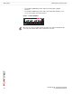
AMC modules FortiGate-5001A security system • The FortiGate-ASM-FB4, provides 4 NP2 accelerated SFP 1-gigabit interfaces. • The FortiGate-ASM-S08, provides adds a removable hard disk that you can use to store log files and content archives. Figure 5: FortiGate-ASM-FB4 HS OOS PWR OT 1 LINK 2 ACT LINK 3 ACT LINK 4 ACT LINK ACT ASM-FB4 Note: You can operate a FortiGate-5001A board with both a FortiGate-RTM-XB2 module and a supported FortiGate AMC module installed at the same time.
Hardware installation Hardware installation Before use, the FortiGate-5001A board must be correctly inserted into an Advanced Telecommunications Computing Architecture (ACTA) chassis such as the FortiGate-5140, FortiGate-5050, or FortiGate-5020 chassis. Before inserting the board into a chassis you should make sure the SW-11 switch is set correctly.
Changing FortiGate-5001A SW11 switch settings Hardware installation Changing FortiGate-5001A SW11 switch settings The SW11 switch on the FortiGate-5001A board is factory set by Fortinet to detect a shelf manager (Figure 6). This is the correct setting if you are installing the FortiGate-5001A board in a chassis that contains an operating shelf manager (such as the FortiGate-5140 or FortiGate-5050 chassis).
Hardware installation Changing FortiGate-5001A SW11 switch settings To change or verify the SW11 switch setting To complete this procedure, you need: ! • A FortiGate-5001A board • A tool for changing the SW11 switch setting (optional) • An electrostatic discharge (ESD) preventive wrist strap with connection cord Caution: FortiGate-5001A boards must be protected from static discharge and physical shock. Only handle or work with FortiGate-5001A boards at a static-free workstation.
FortiGate-5001A mounting components Hardware installation FortiGate-5001A mounting components To install a FortiGate-5001A board you slide the board into an open slot in the front of an ATCA chassis and then use the mounting components to lock the board into place in the slot. When locked into place and positioned correctly the board front panel is flush with the chassis front panel. The board is also connected to the chassis backplane.
Hardware installation Inserting a FortiGate-5001A board Figure 10: FortiGate-5001A-DW left (top) mounting components Alignment Pin Retention Screw Lock AMC Slot Filler Handle Inserting a FortiGate-5001A board The FortiGate-5001A board must be fully installed in a chassis slot, with the handles closed and locked and retention screws fully tightened for the FortiGate-5001A board to receive power and operate normally.
Inserting a FortiGate-5001A board Hardware installation 1 Attach the ESD wrist strap to your wrist and to an available ESD socket or wrist strap terminal. 2 If required, remove the protective metal frame that the FortiGate-5001A board has been shipped in. 3 Insert the FortiGate-5001A board into the empty slot in the chassis. 4 Unlock the handles by squeezing the handle locks. Unlock Handle 5 Open the handles to their fully open positions.
Hardware installation Inserting a FortiGate-5001A board 9 Turn both handles to their fully-closed positions. The handles should hook into the sides of the chassis slot. Closing the handles draws the FortiGate-5001A board into place in the chassis slot and into full contact with the chassis backplane. The FortiGate-5001A front panel should be in contact with the chassis front panel. For the FortiGate-5001A-DW, the right (bottom) handle locks into place.
Removing a FortiGate-5001A board Hardware installation 10 Once the board is inserted correctly, fully tighten the retention screws to lock the FortiGate-5001A board into position in the chassis slot. Retention Screw Tighten Removing a FortiGate-5001A board The following procedure describes how to correctly use the FortiGate-5001A mounting components described in “FortiGate-5001A mounting components” on page 14 to remove a FortiGate-5001A board from an ATCA chassis slot.
Hardware installation Removing a FortiGate-5001A board 3 Fully loosen the retention screws on the FortiGate-5001A front panel. Retention Screw Loosen 4 Unlock the handles by squeezing the handle locks. 5 Open the handles to their fully open positions. ! Caution: To avoid damaging the lock, make sure you squeeze the handles fully to unlock them before opening. The handles should pop easily out of the board front panel.
Resetting a FortiGate-5001A board Hardware installation Resetting a FortiGate-5001A board You must eject the FortiGate-5001A board from the chassis slot to cycle the power and reset the board. See “Removing a FortiGate-5001A board” on page 18 for information about how to eject a FortiGate-5001A board from a chassis.
Hardware installation Installing and removing AMC modules Inserting AMC slot filler panels The following procedure describes how to install a slot filler panel in the FortiGate-5001A front panel AMC opening. The FortiGate-5001A-DW board includes one AMC double-width slot filler panel and the FortiGate-5001A-SW board includes one AMC single-width slot filler panel. ! Caution: Do not operate the FortiGate-5001A board with an open AMC opening.
Installing and removing AMC modules Hardware installation To complete this procedure, you need: ! • A FortiGate-5001A board with an open slot • FortiGate AMC module to install • An electrostatic discharge (ESD) preventive wrist strap with connection cord Caution: FortiGate-5001A boards and FortiGate AMC modules must be protected from static discharge and physical shock. Only handle or work with these components at a static-free workstation.
Hardware installation Troubleshooting ! Caution: FortiGate-5001A boards and FortiGate AMC modules must be protected from static discharge and physical shock. Only handle or work with these components at a static-free workstation. Always wear a grounded electrostatic discharge (ESD) preventive wrist strap when handling these components. 1 Attach the ESD wrist strap to your wrist and to an available ESD socket or wrist strap terminal. 2 Eject the FortiGate-5001A board from the chassis slot.
Troubleshooting Hardware installation FortiGate-5001A status LED is flashing during system operation Normally, the FortiGate-5001A Status LED is off when the FortiGate-5001A board is operating normally. If this LED starts flashing while the board is operating, a fault condition may exist. At the same time the FortiGate-5001A may stop processing traffic. To resolve the problem you can try removing and reinserting the FortiGate-5001A board in the chassis slot. Reloading the firmware may also help.
Quick Configuration Guide Registering your Fortinet product Quick Configuration Guide This section is a quick start guide to connecting and configuring a FortiGate-5001A security system for your network. Before using this chapter, your FortiGate-5000 series or compatible ATCA chassis should be mounted and connected to your power system.
Planning the configuration Quick Configuration Guide NAT/Route mode In NAT/Route mode, the FortiGate-5001A security system is visible to the networks that it is connected to. Each interface connected to a network must be configured with an IP address that is valid for that network. In many configurations, in NAT/Route mode all of the FortiGate interfaces are on different networks, and each network is on a separate subnet.
Quick Configuration Guide Choosing the configuration tool Figure 12: Example FortiGate-5001A board operating in Transparent mode Internet 204.23.1.2 Transparent mode policies controlling traffic between internal and external networks. 192.168.1.1 Gateway to public network FortiGate-5001A board port2 in Transparent mode port1 192.168.1.
Factory default settings Quick Configuration Guide Command Line Interface (CLI) The CLI is a full-featured management tool. Use it to configure the administrator password, the interface addresses, the default gateway, and the DNS server addresses. Requirements: • The serial connector that came packaged with your FortiGate-5001A board. • Terminal emulation application (for example, HyperTerminal for Windows) on the management computer.
Quick Configuration Guide Configuring NAT/Route mode Table 8: FortiGate-5001A board NAT/Route mode settings Admin Administrator Password: port1 port2 IP: _____._____._____._____ Netmask: _____._____._____._____ IP: _____._____._____._____ Netmask: _____._____._____._____ Device (Name of the Interface connected to the external network): Default Route Default Gateway IP address: _____._____._____.
Configuring NAT/Route mode Quick Configuration Guide 3 Set the addressing mode for the interface. (See the online help for information.) • For manual addressing, enter the IP address and netmask for the interface that you added to Table 8 on page 29. • For DHCP addressing, select DHCP and any required settings. • For PPPoE addressing, select PPPoE and enter the username and password and any other required settings.
Quick Configuration Guide Configuring Transparent mode 6 Repeat to configure each interface as required, for example, to configure the port2 interface to the setting that you added to Table 8 on page 29. config system interface edit port2 ... 7 Configure the primary and secondary DNS server IP addresses to the settings that you added to Table 8 on page 29.
Configuring Transparent mode Quick Configuration Guide 4 Type admin in the Name field and select Login. To switch from NAT/Route mode to transparent mode 1 Go to System > Status and select the Change link beside Operation Mode: NAT. 2 Set Operation Mode to Transparent. 3 Set the Management IP/Netmask to the settings that you added to Table 9 on page 31. 4 Set the default Gateway to the setting that you added to Table 9 on page 31.
Quick Configuration Guide Upgrading FortiGate-5001A firmware Upgrading FortiGate-5001A firmware Fortinet periodically updates the FortiGate-5001A FortiOS firmware to include enhancements and address issues. After you have registered your FortiGate-5001A security system (see “Registering your Fortinet product” on page 25) you can download FortiGate-5001A firmware from the support web site http://support.fortinet.com.
FortiGate-5001A base backplane data communication Quick Configuration Guide Where is the name of the firmware image file and is the IP address of the TFTP server. For example, if the firmware image file name is image.out and the IP address of the TFTP server is 192.168.1.168, enter: execute restore image image.out 192.168.1.168 The FortiGate-5001A board responds with the message: This operation will replace the current firmware version! Do you want to continue? (y/n) 6 Type y.
Quick Configuration Guide FortiGate-5001A base backplane data communication In a FortiGate-5140 or FortiGate-5050 chassis, FortiGate-5001A base backplane communication requires one or two FortiSwitch-5003A or FortiSwitch-5003 boards. A FortiSwitch board installed in chassis base slot 1 provides communication on the base1 interface. A FortiSwitch-5003 board installed in chassis base slot 2 provides communication on the base2 interface.
FortiGate-5001A fabric backplane data communication Quick Configuration Guide FortiGate-5001A fabric backplane data communication This section describes how to configure FortiGate-5001A boards for fabric backplane data communication using the fabric1 and fabric2 interfaces.
Quick Configuration Guide Powering off the FortiGate-5001A board To enable fabric backplane data communication from the FortiGate-5001A CLI From the FortiGate-5001A board CLI you can use the following steps to enable fabric backplane data communication. 1 Enter the following command to show the backplane interfaces: config system global set show-backplane-intf enable end The fabric1 and fabric2 backplane interfaces now appear in all Interface lists.
Powering off the FortiGate-5001A board 38 Quick Configuration Guide FortiGate-5001A Security System Guide 01-30000-83456-20081023
For more information Fortinet documentation For more information Support for your Fortinet product is available as online help from within the web-based manager, from the Tools and Documentation CD included with the product, on the Fortinet Technical Documentation web site, from the Fortinet Knowledge Center web site, as well as from Fortinet Technical Support.
© Copyright 2008 Fortinet, Inc. All rights reserved. No part of this publication including text, examples, diagrams or illustrations may be reproduced, transmitted, or translated in any form or by any means, electronic, mechanical, manual, optical or otherwise, for any purpose, without prior written permission of Fortinet, Inc.