FortiGate-5050-R Chassis Guide CONSOLE 2 3 4 5 6 7 8 USB 1 2 3 4 5 6 7 8 STA IPM PWR ACC 1 2 3 4 5 6 7 8 Hot Swap LED MODE LED MODE ETH0 Service INT FLT OK HOT SWAP RESET INT FLT EXT FLT HOT SWAP EXT FLT RESET OK 4 CLK 5000SM 10/100 link/Act 10/100 link/Act POWER STATUS SERIAL 2 ETH0 ETH1 1 3 5 5 6 1 7 8 0 9 10 3 11 12 2 13 14 ZRE ALARM 5050SAP SERIAL 1 CLK 0 2 4 6 8 10 12 ZRE 7 9 11 13 Z R E 2 Z R E 1 Z R E 0 E1 15 14 E1 15
Warnings and cautions Warnings and cautions Only trained and qualified personnel should be allowed to install or maintain FortiGate-5000 series equipment. Read and comply with all warnings, cautions and notices in this document. CAUTION: Risk of Explosion if Battery is replaced by an Incorrect Type. Dispose of Used Batteries According to the Instructions.
Contents Contents Warnings and cautions................................................................................................... 2 FortiGate-5050 chassis............................................................................ 5 FortiGate-5050 front panel ............................................................................................. 6 FortiGate-5050 back panel .............................................................................................
Contents 4 FortiGate-5050-R Chassis Guide 01-30000-87717-20090108 http://docs.fortinet.
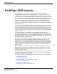
FortiGate-5050 chassis FortiGate-5050 chassis You can install up to five FortiGate-5000 series boards in the five slots of the FortiGate-5050 ATCA chassis. The FortiGate-5050 is a 5U 19-inch rackmount ATCA chassis that contains two redundant DC power connections that connect to -48 VDC Data Center DC power. The FortiGate-5050 chassis also includes a hot swappable cooling fan tray.
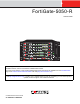
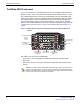
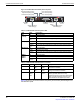
FortiGate-5050 front panel FortiGate-5050 chassis FortiGate-5050 front panel Figure 1 shows the front of a FortiGate-5050 chassis. Two FortiSwitch-5003 boards are installed in slots 1 and 2. Three FortiGate-5001SX boards are installed in slots 3, 4, and 5. The FortiGate-5050 primary and secondary Shelf Managers and the Shelf Alarm Panel (SAP) are also visible.
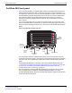
FortiGate-5050 chassis FortiGate-5050 back panel FortiGate-5050 back panel Figure 2 shows the back of a FortiGate-5050 chassis. The FortiGate-5050 chassis back panel includes two redundant -48V to - 58V DC power input connectors labelled Input A and Input B. The power input connectors provide redundant DC power connections for the FortiGate-5050 chassis and distribute DC power to the fan tray and the FortiGate-5000 series boards installed in the FortiGate-5050 chassis.
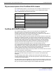
Physical description of the FortiGate-5050 chassis FortiGate-5050 chassis Physical description of the FortiGate-5050 chassis The FortiGate-5050 chassis is a 5U chassis that can be installed in a standard 19-inch rack. Table 1 describes the physical characteristics of the FortiGate-5050 chassis. Table 1: FortiGate-5050 chassis physical description Dimensions 8.75 x 17 x 15.5 in. (13.3 x 43.2 x 39.4 cm) (H x W x D) Shipping weight completely assembled with packaging 26.75 lb. (12.
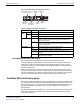
FortiGate-5050 chassis FortiGate-5050 shelf alarm panel Figure 3: FortiGate-5050 shelf manager front panel Retention ETH0 Screw 100base-T Ethernet STATUS RESET ETH0 ETH1 ETH0 Service 5000SM 10/100 link/Act 10/100 link/Act Status LEDs Hot Swap Hot Swap LED ETH 0 and 1 network Reset activity LEDs Button Handle Table 2: FortiGate-5050 shelf manager LEDs LED State Description ETH 0 10/100 ETH 1 link/Act Yellow The Ethernet interface is connected at 100 Mbps.
FortiGate-5050 shelf alarm panel FortiGate-5050 chassis Figure 4: FortiGate-5050 shelf alarm panel front panel Minor Alarm (MIN) (Amber) Major Alarm (MAJ) (Red) Critical Alarm (CRT) (Red) User 3 Alarm (Amber) User 2 Alarm (Amber) User 1 Alarm (Amber) ALARM 5050SAP SERIAL 1 SERIAL 2 Alarm Telco Alarm LED Reset Interface Button Retention Screw Retention Screw SERIAL 2 (Secondary Shelf Manager) SERIAL 1 (Primary Shelf Manager) Table 3: FortiGate-5050 shelf alarm panel LEDs LED State Description
FortiGate-5050 chassis FortiGate-5050 shelf alarm panel Figure 5: Connections between the shelf managers and the shelf alarm panel ALARM 5050SAP Enable Master-Only I²C-bus ShMM-500 Master-Only I²C-bus Buffer LTC4300 I²C-Switch PCA9545 Serial Console Interface CH0 CH3 CH 0 SERIAL 2 Buffer LTC4300 I²C-Switch PCA9545 Enable Serial Console Interface CH3 SERIAL 1 ShMM-500 Secondary Shelf Manager (Left) Primary Shelf Manager (Right) Shelf alarm panel telco alarms The shelf alarm panel telc
Shelf manager command line interface (CLI) FortiGate-5050 chassis Table 5: Telco alarm connector pin assignment Pin Name Description 1 AMIR+ MinorReset+ 2 AMIR- MinorReset- 3 AMAR+ MajorReset+ 4 AMAR- MajorReset- 5 ACNO CriticalAlarm - NO 6 ACNC CriticalAlarm - NC 7 ACCOM CriticalAlarm - COM 8 AMINO MinorAlarm -NO 9 AMINC MinorAlarm - NC 10 AMINCOM MinorAlarm - COM 11 AMANO MajorAlarm - NO 12 AMANC MajorAlarm - NC 13 AMACOM MajorAlarm - COM 14 APRCO PwrAlarm - N
FortiGate-5050 chassis Shelf manager command line interface (CLI) Figure 7: Connecting to a shelf manager serial port FortiGate-5050 Shelf Alarm Panel ALARM 5050SAP SERIAL 1 SERIAL1 (Primary Shelf Manager) SERIAL 2 Fortinet RJ-45 to 9-pin Console Cable SERIAL2 (Secondary Shelf Manager) To PC RS-232 Console Port To connect to the shelf manager CLI using a shelf alarm panel serial port 1 Connect the Fortinet console cable to the shelf alarm panel Serial 1 or Serial 2 port (see Figure 7).
Shelf manager command line interface (CLI) FortiGate-5050 chassis 2 Enter and confirm a new password for the root account. The password should be between 5 and 8 characters long and should include a combination of upper and lower case letters and numbers. You can use the passwd command to change the root account password at any time. You can also use the passwd command to remove the root account. Enter the passwd command and when prompted for a password, press enter to add a blank password.
Power connection and configuration Power connection and configuration This chapter describes how to connect data center DC power to a FortiGate-5050 chassis. If data center DC power is not available, this document also describes how to use the FortiGate-5053 power converter tray to supply DC power to the FortiGate-5050 chassis.
Connecting the FortiGate-5050 chassis to data center DC power and data center ground Figure 8: Connecting a FortiGate-5050 power input connector to data center DC power Data Center RTN connector Data Center -48VDC connector RTN (positive) red to Data Center RTN -48V (-DC in) black to Data Center -48VDC -48V RTN (-DC IN) INPUT A 24 AMP Power wire fixture Positive (RTN) (red) -48 (-DC in) (black) To connect a FortiGate-5050 power input connector to data center DC power You need the following tools an
Power connection and configuration Connecting the FortiGate-5050 chassis to data center ground The FortiGate-5050 chassis has a ground connections on the lower left side of the FortiGate-5050 back panel (see Figure 2 on page 7). This connector must be connected to data center ground. To connect the FortiGate-5050 chassis to data center ground You need the following tools and equipment to connect the FortiGate-5050 chassis to ground: • A number 2 Phillips screwdriver.
Connecting the FortiGate-5050 chassis to AC power using the FortiGate-5053 power converter tray FortiGate-5053 power converter tray front and back panel The front panel of the FortiGate-5053 power converter tray (shown in Figure 10) provides access to the FortiGate-5020/5050 power supplies.
Power connection and configuration The back panel also includes three AC power connectors numbered 1, 2, 3. The AC connector numbering corresponds to the slot numbering showing in Figure 10. Each connector connects AC power directly to a FortiGate-5020/5050 power supply. The FortiGate-5053 can contain 1, 2, or 3 FortiGate-5020/5050 power supplies depending on your requirements. You should only connect AC power to the power supplies that are installed.
Connecting the FortiGate-5050 chassis to AC power using the FortiGate-5053 power converter tray Figure 12: Non-redundant power for all FortiGate-5050 chassis slots 1 FortiGate-5053 power convertor tray Slot 3 Slot 2 Slot 1 2 FortiGate-5020/5050 power supplies 2 x 800W = 1600W USB 1 2 3 4 5 6 7 8 CONSOLE USB 1 2 3 4 5 6 7 8 CONSOLE USB 1 2 3 4 5 6 7 8 STA IPM STA IPM PWR ACC MANAGEMENT E T H O 2 E T H O ETH0 ETH1 SERIAL 2 POWER SMC Hot Swap OK INT FLT 5000SM 10/
Power connection and configuration Figure 14: Redundant FortiGate-5053 power converter trays Slot 3 Slot 2 Slot 1 Slot 3 Slot 2 Slot 1 2 FortiGate-5053 power convertor trays 4 FortiGate-5020/5050 power supplies 2 x 800W = 1600W 2 x 800W = 1600W 2 3 4 5 6 7 8 1 2 3 4 5 6 7 8 CONSOLE USB 1 2 3 4 5 6 7 8 STA IPM PWR ACC MANAGEMENT E T H O 2 MANAGEMENT E T H O SMC Hot Swap INT FLT ETH0 ETH1 SERIAL 2 POWER STATUS OK LED MODE INT FLT 5000SM 10/100 link/Act 10/1
Connecting the FortiGate-5050 chassis to AC power using the FortiGate-5053 power converter tray Connecting a FortiGate-5050 chassis to the FortiGate-5053 power converter tray To use a FortiGate-5053 power converter tray with the FortiGate-5050 chassis you need to make DC power connections between the FortiGate-5050 chassis and the FortiGate5053 power converter tray. You also need to the connect the FortiGate-5050 chassis to data center ground.
Power connection and configuration Figure 16: Connecting a FortiGate-5050 power input connector to a FortiGate-5053 power converter tray V-48V (BLACK) V+ (RTN) (RED) AC in Red RTN to FortiGate-5053 RTN Black -48V VDC to FortiGate-5053 -48 VDC -48V RTN (-DC IN) INPUT A Power wire fixture 24 AMP -48V (-DC in) Positive (RTN) (red) (black) 7 Make sure the power wires are secured to the chassis using the power wire fixture and tie wraps if required. 8 If required, label the black wires -48V.
Turning on FortiGate-5050 chassis power Figure 17: Wiring the FortiGate-5053 power converter tray To connect the FortiGate-5050 chassis to data center ground The FortiGate-5053 power converter tray does not have a ground connector. So, even if you are using a FortiGate-5053 power converter tray to supply DC power to your FortiGate-5050, you must use the procedure “To connect the FortiGate-5050 chassis to data center ground” on page 17 to connect the FortiGate-5050 to data center ground.
FortiGate-5050 hardware procedures Mounting the FortiGate-5050 chassis FortiGate-5050 hardware procedures This chapter assumes the chassis has been mounted and connected to a power source as detailed in “Power connection and configuration” on page 15.
Using FortiSwitch-5003A and FortiSwitch-5003 boards for backplane communication FortiGate-5050 hardware procedures Caution: FortiGate-5000 series and FortiSwitch-5000 series modules must be protected from static discharge and physical shock. Only handle or work with FortiGate-5000 series and FortiSwitch-5000 series modules at a static-free workstation.
For more information Fortinet documentation For more information Support for your Fortinet product is available as online help from within the web-based manager, from the Tools and Documentation CD included with the product, on the Fortinet Technical Documentation web site, from the Fortinet Knowledge Center web site, as well as from Fortinet Technical Support.
Register your Fortinet product For more information © Copyright 2009 Fortinet, Inc. All rights reserved. No part of this publication including text, examples, diagrams or illustrations may be reproduced, transmitted, or translated in any form or by any means, electronic, mechanical, manual, optical or otherwise, for any purpose, without prior written permission of Fortinet, Inc.