FortiGate-5050 Chassis Guide CONSOLE 5 PWR ACC 4 PWR ACC 1 2 3 4 5 6 8 CONSOLE USB 1 2 3 4 5 6 7 8 CONSOLE USB 1 2 3 4 5 6 7 8 STA IPM STA IPM LED MODE INT FLT OK RESET POWER LED MODE 1 0 RESET 3 2 INT FLT 5 4 EXT FLT 7 6 OK 9 8 CLK 11 10 HOT SWAP 1 3 5 7 13 12 ZRE 15 14 ShMC HOT SWAP EXT FLT CLK 0 2 4 6 8 10 12 14 E1 E2 Z R E 2 Z R E 1 Z R E 0 R S 2 3 2 E2 ZRE 9 11 13 15 Z R E 2 E1 Z R E 1 Z R E 0 R S 2 3 2 SYSTEM CONSOL
Warnings and cautions Warnings and cautions Only trained and qualified personnel should be allowed to install or maintain FortiGate-5000 series equipment. Read and comply with all warnings, cautions and notices in this document. CAUTION: Risk of Explosion if Battery is replaced by an Incorrect Type. Dispose of Used Batteries According to the Instructions.
Contents Contents Warnings and cautions................................................................................................... 2 FortiGate-5050 chassis............................................................................ 5 FortiGate-5050 front panel ............................................................................................. 6 FortiGate-5050 back panel .............................................................................................
Contents 4 FortiGate-5050 Chassis Guide 01-30000-87211-20090106 http://docs.fortinet.
FortiGate-5050 chassis FortiGate-5050 chassis You can install up to five FortiGate-5000 series boards in the five slots of the FortiGate-5050 ATCA chassis. The FortiGate-5050 is a 5U 19-inch rackmount ATCA chassis that contains two redundant DC power connections that connect to -48 VDC Data Center DC power. The FortiGate-5050 chassis also includes a hot swappable cooling fan tray.
FortiGate-5050 front panel FortiGate-5050 chassis FortiGate-5050 front panel Figure 1 shows the front of a FortiGate-5050 chassis. Two FortiSwitch-5003 boards are installed in slots 1 and 2. Three FortiGate-5001SX boards are installed in slots 3, 4, and 5. The FortiGate-5050 primary Shelf Manager is also visible. The factory-installed shelf managers provide power distribution, cooling, alarms, shelf status, and a telco alarm interface for the FortiGate-5050 chassis.
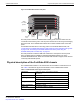
FortiGate-5050 chassis Physical description of the FortiGate-5050 chassis Figure 2: FortiGate-5050 chassis back panel 5 4 RTM slot filler panels 3 2 RTN Power wire -48V DC VOLTAGE RANGE -48V TO -58V RTN (-DC IN) GND Ground Connector (green) RTN 1 INPUT A -48V DC VOLTAGE RANGE -48V TO -58V RTN (-DC IN) INPUT B 25 AMP Positive (RTN) (red) -48V to -58V Positive (-DC in) (RTN) (black) (red) 25 AMP -48V to -58V (-DC in) (black) ESD k t The back panel includes the FortiGate-5050 chassis g
FortiGate-5050 shelf manager FortiGate-5050 chassis FortiGate-5050 shelf manager The FortiGate-5050 chassis includes one or two identical redundant hot-swappable shelf managers (also called shelf manager cards (SMCs)), located in the dedicated shelf manager slots on the bottom of the FortiGate-5050 front panel. The primary shelf manager is installed on the right (SMC 1) the secondary shelf manager is installed on the left (SMC 2).
FortiGate-5050 chassis FortiGate-5050 shelf manager Shelf manager command line interface (CLI) You can use the shelf manager CLI to communicate with the intelligent management controllers of the chassis, with boards in the chassis, and with the shelf manager itself. The CLI is an IPMI-based set of commands that can be accessed directly or through a higher-level management application or a script.
FortiGate-5050 shelf manager FortiGate-5050 chassis 7 At the login prompt enter the shelf manager user name and password. The default user name is root with no password. When you log into the shelf manager CLI you are logging into a Linux shell as root. The following message appears.
FortiGate-5050 chassis FortiGate-5050 shelf manager For example, you can enter the following command to list the most commonly used CLIA commands: clia help You can also the help command to get more information about specific CLIA commands.
FortiGate-5050 shelf manager FortiGate-5050 chassis Table 4: Telco alarm connector pin assignment Pin Name Description 1 AMIR+ MinorReset+ 2 AMIR- MinorReset- 3 AMAR+ MajorReset+ 4 AMAR- MajorReset- 5 ACNO CriticalAlarm - NO 6 ACNC CriticalAlarm - NC 7 ACCOM CriticalAlarm - COM 8 AMINO MinorAlarm -NO 9 AMINC MinorAlarm - NC 10 AMINCOM MinorAlarm - COM 11 AMANO MajorAlarm - NO 12 AMANC MajorAlarm - NC 13 AMACOM MajorAlarm - COM 14 APRCO PwrAlarm - NO 15 APRCOM
Power connection and configuration Power connection and configuration This chapter describes how to connect data center DC power to a FortiGate-5050 chassis. If data center DC power is not available, this document also describes how to use the FortiGate-5053 power converter tray to supply DC power to the FortiGate-5050 chassis.
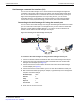
Connecting the FortiGate-5050 chassis to data center DC power and data center ground Figure 6: Connecting a FortiGate-5050 power input connector to data center DC power Data Center RTN connector Data Center -48VDC connector RTN (positive) red to Data Center RTN -48V to -58V (-DC in) black to Data Center -48VDC Power wire fixture Positive (RTN) (red) -48V to -58V (-DC in) (black) To connect a FortiGate-5050 power input connector to data center DC power You need the following tools and equipment to co
Power connection and configuration To connect the FortiGate-5050 chassis to data center ground You need the following tools and equipment to connect the FortiGate-5050 chassis to ground: • A number 2 Phillips screwdriver. • An electrostatic discharge (ESD) preventive wrist or ankle strap with connection cord. • One green AWG-6 stranded wire with terminal lugs attached.
Connecting the FortiGate-5050 chassis to AC power using the FortiGate-5053 power converter tray Figure 8: Front panel of the FortiGate-5053 power converter tray with one power supply removed AC Power LED DC Power LED Slot 3 Slot 1 Slot 2 The LEDs for each installed power supply are visible from the FortiGate-5053 power converter tray front panel. Table 5: FortiGate-5020/5050 power supply LEDs LED State Description AC Power Green The power supply is connected to AC power.
Power connection and configuration AC input power characteristics: • AC input voltage: 110 to 250 VAC • AC input current: 10A • Frequency: 47 to 63 Hz Selecting the power supplies and power converter trays that you need for your FortiGate-5050 configuration This section provides some basic information for determining how many FortiGate-5053 power converter trays and FortiGate-5020/5050 power supplies that you need, depending on the power requirements of your FortiGate-5050 chassis.
Connecting the FortiGate-5050 chassis to AC power using the FortiGate-5053 power converter tray Figure 10: Non-redundant power for all FortiGate-5050 chassis slots 1 FortiGate-5053 power convertor tray Slot 3 Slot 2 Slot 1 2 FortiGate-5020/5050 power supplies 2 x 800W = 1600W 5 USB 1 2 3 4 5 6 7 8 CONSOLE USB 1 2 3 4 5 6 7 8 CONSOLE USB 1 2 3 4 5 6 7 8 STA IPM STA IPM OK INT FLT LED MODE POWER LED MODE 1 5 3 HOT SWAP ZRE 0 4 2 CLK EXT FLT OK 1 INT FLT 5
Power connection and configuration Figure 12: Redundant FortiGate-5053 power converter trays Slot 3 Slot 2 Slot 1 Slot 3 Slot 2 Slot 1 2 FortiGate-5053 power convertor trays 4 FortiGate-5020/5050 power supplies 2 x 800W = 1600W 2 x 800W = 1600W 5 USB 1 2 3 4 5 6 7 8 CONSOLE USB 1 2 3 4 5 6 7 8 CONSOLE USB 1 2 3 4 5 6 7 8 STA IPM STA IPM OK INT FLT 1 LED MODE POWER LED MODE OK INT FLT 6 ZRE CLK EXT FLT ShMC RESET 7 5 3 ZRE 0 6 4 2 CLK 1 EXT FL
Connecting the FortiGate-5050 chassis to AC power using the FortiGate-5053 power converter tray Connecting a FortiGate-5050 chassis to the FortiGate-5053 power converter tray To use a FortiGate-5053 power converter tray with the FortiGate-5050 chassis you need to make DC power connections between the FortiGate-5050 chassis and the FortiGate5053 power converter tray. You also need to the connect the FortiGate-5050 chassis to data center ground.
Power connection and configuration Figure 14: Connecting a FortiGate-5050 power input connector to a FortiGate-5053 power converter tray V+ (RTN) (RED) V-48V (BLACK) AC in Red RTN to FortiGate-5053 RTN -48V/-58 VDC black to FortiGate-5053 -48/-58 VDC Power wire fixture -48V/-58V -DC in Positive (RTN) (red) (black) 7 Make sure the power wires are secured to the chassis using the power wire fixture and tie wraps if required. 8 If required, label the black wires -48V.
Turning on FortiGate-5050 chassis power Figure 15: Wiring the FortiGate-5053 power converter tray To connect the FortiGate-5050 chassis to data center ground The FortiGate-5053 power converter tray does not have a ground connector. So, even if you are using a FortiGate-5053 power converter tray to supply DC power to your FortiGate-5050, you must use the procedure “To connect the FortiGate-5050 chassis to data center ground” on page 15 to connect the FortiGate-5050 to data center ground.
FortiGate-5050 hardware procedures Mounting the FortiGate-5050 chassis FortiGate-5050 hardware procedures This chapter assumes the chassis has been mounted and connected to a power source as detailed in “Power connection and configuration” on page 13.
Using FortiSwitch-5003A and FortiSwitch-5003 boards for backplane communication FortiGate-5050 hardware procedures Caution: FortiGate-5000 series and FortiSwitch-5000 series boards must be protected from static discharge and physical shock. Only handle or work with FortiGate-5000 series and FortiSwitch-5000 series boards at a static-free workstation. Always wear a grounded electrostatic discharge (ESD) preventive wrist or ankle strap when handling FortiGate-5000 series or FortiSwitch-5000 series boards.
For more information Fortinet documentation For more information Support for your Fortinet product is available as online help from within the web-based manager, from the Tools and Documentation CD included with the product, on the Fortinet Technical Documentation web site, from the Fortinet Knowledge Center web site, as well as from Fortinet Technical Support.
Register your Fortinet product For more information © Copyright 2009 Fortinet, Inc. All rights reserved. No part of this publication including text, examples, diagrams or illustrations may be reproduced, transmitted, or translated in any form or by any means, electronic, mechanical, manual, optical or otherwise, for any purpose, without prior written permission of Fortinet, Inc.