Installation and Configuration Guide FortiGate 50A PWR STATUS A INTERNAL EXTERNAL LINK 100 LINK 100 FortiGate User Manual Volume 1 Version 2.
© Copyright 2004 Fortinet Inc. All rights reserved. No part of this publication including text, examples, diagrams or illustrations may be reproduced, transmitted, or translated in any form or by any means, electronic, mechanical, manual, optical or otherwise, for any purpose, without prior written permission of Fortinet Inc. FortiGate-50A Installation and Configuration Guide Version 2.
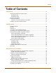
Contents Table of Contents Introduction .......................................................................................................... 13 NAT/Route mode and Transparent mode......................................................................... NAT/Route mode .......................................................................................................... Transparent mode.........................................................................................................
Contents Completing the configuration ............................................................................................ Setting the date and time .............................................................................................. Changing antivirus protection ....................................................................................... Registering your FortiGate unit .....................................................................................
Contents Shutting down the FortiGate unit ...................................................................................... System status ................................................................................................................... Viewing CPU and memory status ................................................................................. Viewing sessions and network status ...........................................................................
Contents Network configuration......................................................................................... 93 Configuring interfaces ....................................................................................................... 93 Viewing the interface list ............................................................................................... 94 Changing the administrative status of an interface .......................................................
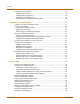
Contents Changing system options................................................................................................ Adding and editing administrator accounts ..................................................................... Adding new administrator accounts ............................................................................ Editing administrator accounts.................................................................................... Configuring SNMP ...........................
Contents Virtual IPs........................................................................................................................ Adding static NAT virtual IPs ...................................................................................... Adding port forwarding virtual IPs ............................................................................... Adding policies with virtual IPs.................................................................................... IP pools ............
Contents AutoIKE IPSec VPNs ...................................................................................................... General configuration steps for an AutoIKE VPN ....................................................... Adding a phase 1 configuration for an AutoIKE VPN.................................................. Adding a phase 2 configuration for an AutoIKE VPN.................................................. Managing digital certificates................................................
Contents Logging attacks............................................................................................................... 222 Logging attack messages to the attack log................................................................. 222 Reducing the number of NIDS attack log and email messages.................................. 222 Antivirus protection........................................................................................... 225 General configuration steps ...................
Contents Email block list ................................................................................................................ Adding address patterns to the email block list........................................................... Downloading the email block list ................................................................................. Uploading an email block list ...................................................................................... Email exempt list................
Contents 12 Fortinet Inc.
FortiGate-50A Installation and Configuration Guide Version 2.50 Introduction The FortiGate-50A Antivirus Firewall is an easy-to-deploy and easy-toadminister solution that delivers exceptional value and performance for small office and home office (SOHO) applications.
Document conventions Introduction Document conventions This guide uses the following conventions to describe CLI command syntax. • angle brackets < > to indicate variable keywords For example: execute restore config You enter restore config myfile.bak indicates an ASCII string variable keyword. indicates an integer variable keyword. indicates an IP address variable keyword.
Introduction Fortinet documentation Fortinet documentation Information about FortiGate products is available from the following FortiGate User Manual volumes: • Volume 1: FortiGate Installation and Configuration Guide Describes installation and basic configuration for the FortiGate unit.
Customer service and technical support Introduction Customer service and technical support For antivirus and attack definition updates, firmware updates, updated product documentation, technical support information, and other resources, please visit the Fortinet technical support web site at http://support.fortinet.com. You can also register FortiGate Antivirus Firewalls from http://support.fortinet.com and modify your registration information at any time.
FortiGate-50A Installation and Configuration Guide Version 2.50 Getting started This chapter describes unpacking, setting up, and powering on a FortiGate Antivirus Firewall unit. When you have completed the procedures in this chapter, you can proceed to one of the following: • If you are going to operate the FortiGate unit in NAT/Route mode, go to “NAT/Route mode installation” on page 33.
Package contents Getting started Package contents The FortiGate-50A package contains the following items: • the FortiGate-50A Antivirus Firewall • one orange cross-over ethernet cable • one gray regular ethernet cable • one null-modem cable • FortiGate-50A QuickStart Guide • A CD containing the FortiGate user documentation • one AC adapter Figure 1: FortiGate-50A package contents Front Ethernet Cables: Orange - Crossover Grey - Straight-through PWR STATUS PWR STATUS A Power Status LED LE
Getting started Powering on Environmental specifications • Operating temperature: 32 to 104°F (0 to 40°C) • Storage temperature: -13 to 158°F (-25 to 70°C) • Humidity: 5 to 95% non-condensing Powering on To power on the FortiGate-50A unit 1 Connect the AC adapter to the power connection at the back of the FortiGate-50 unit. 2 Connect the AC adapter to a power outlet. The FortiGate-50A starts up. The Power and Status lights light.
Connecting to the command line interface (CLI) Getting started To connect to the web-based manager 1 Set the IP address of the computer with an ethernet connection to the static IP address 192.168.1.2 and a netmask of 255.255.255.0. You can also configure the management computer to obtain an IP address automatically using DHCP. The FortiGate DHCP server assigns the management computer an IP address in the range 192.168.1.1 to 192.168.1.254.
Getting started Connecting to the command line interface (CLI) Note: The following procedure describes how to connect to the CLI using Windows HyperTerminal software. You can use any terminal emulation program. To connect to the CLI 1 Connect the null modem cable to the communications port of your computer and to the FortiGate Console port. 2 Make sure that the FortiGate unit is powered on. 3 Start HyperTerminal, enter a name for the connection, and select OK.
Factory default FortiGate configuration settings Getting started Factory default FortiGate configuration settings The FortiGate unit is shipped with a factory default configuration. The default configuration allows you to connect to and use the FortiGate web-based manager to configure the FortiGate unit onto the network. To configure the FortiGate unit onto the network you add an administrator password, change network interface IP addresses, add DNS server IP addresses, and configure routing, if required.
Getting started Factory default FortiGate configuration settings Factory default NAT/Route mode network configuration When the FortiGate unit is first powered on, it is running in NAT/Route mode and has the basic network configuration listed in Table 3. This configuration allows you to connect to the FortiGate unit web-based manager and establish the configuration required to connect the FortiGate unit to the network.
Factory default FortiGate configuration settings Getting started Table 5: Factory default firewall configuration (Continued) Recurring Always Schedule The schedule is valid at all times. This means that the firewall policy is valid at all times. Firewall Policy Firewall policy for connections from the internal network to the external network. Int->Ext Source Internal_All Destination External_All The policy destination address.
Getting started Factory default FortiGate configuration settings Factory default content profiles You can use content profiles to apply different protection settings for content traffic that is controlled by firewall policies.
Factory default FortiGate configuration settings Getting started Scan content profile Use the scan content profile to apply antivirus scanning to HTTP, FTP, IMAP, POP3, and SMTP content traffic.
Getting started Planning the FortiGate configuration Unfiltered content profile Use the unfiltered content profile if you do not want to apply content protection to traffic. You can add this content profile to firewall policies for connections between highly trusted or highly secure networks where content does not need to be protected.
Planning the FortiGate configuration Getting started You typically use NAT/Route mode when the FortiGate unit is operating as a gateway between private and public networks. In this configuration, you would create NAT mode policies to control traffic flowing between the internal, private network and the external, public network (usually the Internet). Figure 3: Example NAT/Route mode network configuration External 204.23.1.5 FortiGate-50A Unit in NAT/Route mode Internal 192.168.1.
Getting started Planning the FortiGate configuration In NAT/Route mode you can also change the configuration of the FortiGate DHCP server to supply IP addresses for the computers on your internal network. You can also configure the FortiGate to allow Internet access to your internal Web, FTP, or email servers.
FortiGate model maximum values matrix Getting started FortiGate model maximum values matrix Table 10: FortiGate maximum values matrix FortiGate model 50A 60 100 200 300 400 500 800 1000 3000 3600 4000 Routes 500 500 500 500 500 500 500 500 500 500 500 500 Policy routing gateways 500 500 500 500 500 500 500 500 500 500 500 500 Administrative users 500 500 500 500 500 500 500 500 500 500 500 500 VLAN subinterfaces N/A N/A N/A 4096* 4096* 4096* 4096*
Getting started Next steps Table 10: FortiGate maximum values matrix FortiGate model 50A 60 100 200 300 400 500 800 1000 3000 3600 4000 IPSec remote gateways (Phase 1) 20 50 80 200 1500 1500 3000 3000 5000 5000 5000 5000 IPSec VPN tunnels (Phase 2) 20 50 80 200 1500 1500 3000 3000 5000 5000 5000 5000 IPSec VPN concentrators 500 500 500 500 500 500 500 500 500 500 500 500 PPTP users 500 500 500 500 500 500 500 500 500 500 500 500 L2TP users 5
Next steps 32 Getting started Fortinet Inc.
FortiGate-50A Installation and Configuration Guide Version 2.50 NAT/Route mode installation This chapter describes how to install the FortiGate unit in NAT/Route mode. To install the FortiGate unit in Transparent mode, see “Transparent mode installation” on page 41.
Preparing to configure NAT/Route mode NAT/Route mode installation To use the factory default configuration, follow these steps to install the FortiGate unit: 1 Configure the TCP/IP settings of the computers on your internal network to obtain an IP address automatically using DHCP. Refer to your computer documentation for assistance. 2 Complete the procedure in the section “Connecting the FortiGate unit to your networks” on page 37.
NAT/Route mode installation Using the setup wizard Advanced NAT/Route mode settings Use Table 13 to gather the information that you need to customize advanced FortiGate NAT/Route mode settings. Table 13: Advanced FortiGate NAT/Route mode settings DHCP server Starting IP: _____._____._____._____ Ending IP: _____._____._____._____ Netmask: _____._____._____._____ Default Route: _____._____._____._____ DNS IP: _____._____._____.
Using the command line interface NAT/Route mode installation Using the command line interface As an alternative to using the setup wizard, you can configure the FortiGate unit using the command line interface (CLI). To connect to the CLI, see “Connecting to the command line interface (CLI)” on page 20. Configuring the FortiGate unit to operate in NAT/Route mode Use the information that you gathered in Table 12 on page 34 to complete the following procedures.
NAT/Route mode installation Connecting the FortiGate unit to your networks 6 Optionally, set the secondary DNS server IP addresses. Enter set system dns secondary Example set system dns secondary 293.44.75.22 7 Set the default route to the Default Gateway IP address (not required for DHCP and PPPoE). set system route number dst 0.0.0.0 0.0.0.0 gw1 Example set system route number 0 dst 0.0.0.0 0.0.0.0 gw1 204.23.1.
Configuring your networks NAT/Route mode installation To connect the FortiGate-50A unit: 1 Connect the Internal interface to the hub or switch connected to your internal network. 2 Connect the External interface to the Internet. Connect to the public switch or router provided by your Internet Service Provider. If you are a DSL or cable subscriber, connect the External interface to the internal or LAN connection of your DSL or cable modem.
NAT/Route mode installation Completing the configuration Registering your FortiGate unit After purchasing and installing a new FortiGate unit, you can register the unit by going to System > Update > Support, or using a web browser to connect to http://support.fortinet.com and selecting Product Registration. Registration consists of entering your contact information and the serial numbers of the FortiGate units you or your organization have purchased. Registration is quick and easy.
Completing the configuration 40 NAT/Route mode installation Fortinet Inc.
FortiGate-50A Installation and Configuration Guide Version 2.50 Transparent mode installation This chapter describes how to install your FortiGate unit in Transparent mode. If you want to install the FortiGate unit in NAT/Route mode, see “NAT/Route mode installation” on page 33.
Using the setup wizard Transparent mode installation Using the setup wizard From the web-based manager, you can use the setup wizard to create the initial configuration of your FortiGate unit. To connect to the web-based manager, see “Connecting to the web-based manager” on page 19. Changing to Transparent mode The first time that you connect to the FortiGate unit, it is configured to run in NAT/Route mode. To switch to Transparent mode using the web-based manager: 1 Go to System > Status.
Transparent mode installation Connecting the FortiGate unit to your networks Changing to Transparent mode 1 Log into the CLI if you are not already logged in. 2 Switch to Transparent mode. Enter: set system opmode transparent After a few seconds, the login prompt appears. 3 Type admin and press Enter. The following prompt appears: Type ? for a list of commands. 4 Confirm that the FortiGate unit has switched to Transparent mode.
Connecting the FortiGate unit to your networks Transparent mode installation To connect the FortiGate unit: 1 Connect the Internal interface to the hub or switch connected to your internal network. 2 Connect the External interface to the Internet. Connect to the public switch or router provided by your Internet Service Provider.
Transparent mode installation Completing the configuration Completing the configuration Use the information in this section to complete the initial configuration of the FortiGate unit. Setting the date and time For effective scheduling and logging, the FortiGate system date and time should be accurate. You can either manually set the date and time or you can configure the FortiGate unit to automatically keep its date and time correct by synchronizing with a Network Time Protocol (NTP) server.
Transparent mode configuration examples Transparent mode installation Transparent mode configuration examples A FortiGate unit operating in Transparent mode still requires a basic configuration to operate as a node on the IP network. As a minimum, the FortiGate unit must be configured with an IP address and subnet mask. These are used for management access and to allow the unit to receive antivirus and definitions updates.
Transparent mode installation Transparent mode configuration examples Example default route to an external network Figure 7 shows a FortiGate unit where all destinations, including the management computer, are located on the external network. To reach these destinations, the FortiGate unit must connect to the “upstream” router leading to the external network. To facilitate this connection, you must enter a single default route that points to the upstream router as the next hop/default gateway.
Transparent mode configuration examples Transparent mode installation Web-based manager example configuration steps To configure basic Transparent mode settings and a default route using the web-based manager: 1 Go to System > Status. • Select Change to Transparent Mode. • Select Transparent in the Operation Mode list. • Select OK. The FortiGate unit changes to Transparent mode. 2 Go to System > Network > Management. • Change the Management IP and Netmask: IP: 192.168.1.1 Mask: 255.255.255.
Transparent mode installation Transparent mode configuration examples Note: This is an example configuration only. To configure a static route, you require a destination IP address. Figure 8: Static route to an external destination 24.102.233.5 FortiResponse Distribution Network (FDN) Internet Upstream Router Gateway IP 192.168.1.2 DNS DMZ Management IP 192.168.1.
Transparent mode configuration examples Transparent mode installation Web-based manager example configuration steps To configure the basic FortiGate settings and a static route using the web-based manager: 1 Go to System > Status. • Select Change to Transparent Mode. • Select Transparent in the Operation Mode list. • Select OK. The FortiGate unit changes to Transparent mode. 2 Go to System > Network > Management. • Change the Management IP and Netmask: IP: 192.168.1.1 Mask: 255.255.255.
Transparent mode installation Transparent mode configuration examples Example static route to an internal destination Figure 9 shows a FortiGate unit where the FDN is located on an external subnet and the management computer is located on a remote, internal subnet. To reach the FDN, you need to enter a single default route that points to the upstream router as the next hop/default gateway. To reach the management computer, you need to enter a single static route that leads directly to it.
Transparent mode configuration examples 4 Transparent mode installation Configure the default route to the external network. Web-based manager example configuration steps To configure the FortiGate basic settings, a static route, and a default route using the web-based manager: 1 Go to System > Status. • Select Change to Transparent Mode. • Select Transparent in the Operation Mode list. • Select OK. The FortiGate unit changes to Transparent mode. 2 Go to System > Network > Management.
FortiGate-50A Installation and Configuration Guide Version 2.50 System status You can connect to the web-based manager and view the current system status of the FortiGate unit. The status information that is displayed includes the current firmware version, the current virus and attack definitions, and the FortiGate unit serial number.
Changing the FortiGate host name System status Changing the FortiGate host name The FortiGate host name appears on the Status page and in the FortiGate CLI prompt. The host name is also used as the SNMP system name. For information about the SNMP system name, see “Configuring SNMP” on page 125. The default host name is FortiGate-50A. To change the FortiGate host name 1 Go to System > Status. 2 Select Edit Host Name 3 Type a new host name. 4 Select OK.
System status Changing the FortiGate firmware Upgrading to a new firmware version Use the following procedures to upgrade the FortiGate unit to a newer firmware version. Upgrading the firmware using the web-based manager Note: Installing firmware replaces the current antivirus and attack definitions with the definitions included with the firmware release that you are installing.
Changing the FortiGate firmware System status 4 Make sure the FortiGate unit can connect to the TFTP server. You can use the following command to ping the computer running the TFTP server. For example, if the IP address of the TFTP server is 192.168.1.168: execute ping 192.168.1.
System status Changing the FortiGate firmware If you are reverting to a previous FortiOS version (for example, reverting from FortiOS v2.50 to FortiOS v2.36) you might not be able to restore the previous configuration from the backup configuration file. Note: Installing firmware replaces the current antivirus and attack definitions with the definitions included with the firmware release that you are installing.
Changing the FortiGate firmware System status Note: Installing firmware replaces the current antivirus and attack definitions with the definitions included with the firmware release that you are installing. After you install new firmware, use the procedure “Manually initiating antivirus and attack definitions updates” on page 75 to make sure that antivirus and attack definitions are up to date. You can also use the CLI command execute updatecenter updatenow to update the antivirus and attack definitions.
System status Changing the FortiGate firmware 12 To confirm that the antivirus and attack definitions have been updated, enter the following command to display the antivirus engine, virus and attack definitions version, contract expiry, and last update attempt information. get system objver Installing firmware images from a system reboot using the CLI This procedure installs a specified firmware image and resets the FortiGate unit to default settings.
Changing the FortiGate firmware System status 6 Enter the following command to restart the FortiGate unit: execute reboot As the FortiGate units starts, a series of system startup messages is displayed. When one of the following messages appears: Press any key to enter configuration menu..... ...... 7 Immediately press any key to interrupt the system startup. Note: You have only 3 seconds to press any key.
System status Changing the FortiGate firmware Restoring the previous configuration Change the internal interface addresses if required. You can do this from the CLI using the command: set system interface After changing the interface addresses, you can access the FortiGate unit from the web-based manager and restore the configuration. • To restore the FortiGate unit configuration, see “Restoring system settings” on page 64.
Changing the FortiGate firmware System status 5 Enter the following command to restart the FortiGate unit: execute reboot 6 As the FortiGate unit reboots, press any key to interrupt the system startup. As the FortiGate units starts, a series of system startup messages are displayed. When one of the following messages appears: Press any key to enter configuration menu..... ...... 7 Immediately press any key to interrupt the system startup. Note: You have only 3 seconds to press any key.
System status Manual virus definition updates Manual virus definition updates The Status page of the FortiGate web-based manager displays the current installed versions of the FortiGate antivirus definitions. Note: For information about configuring the FortiGate unit for automatic antivirus definitions updates, see “Virus and attack definitions updates and registration” on page 73. You can also manually start an antivirus definitions update by going to System > Update and selecting Update Now.
Displaying the FortiGate serial number System status Displaying the FortiGate serial number 1 Go to System > Status. The serial number is displayed on the System Status page of the web-based manager. The serial number is specific to the FortiGate unit and does not change with firmware upgrades. Displaying the FortiGate up time 1 Go to System > Status. The FortiGate up time displays the time in days, hours, and minutes since the FortiGate unit was last started.
System status Restoring system settings to factory defaults Restoring system settings to factory defaults Use the following procedure to restore system settings to the values set at the factory. This procedure does not change the firmware version or the antivirus or attack definitions. ! Caution: This procedure deletes all changes that you have made to the FortiGate configuration and reverts the system to its original configuration, including resetting interface addresses.
Changing to NAT/Route mode System status Changing to NAT/Route mode Use the following procedure to change the FortiGate unit from Transparent mode to NAT/Route mode. After you change the FortiGate unit to NAT/Route mode, most of the configuration resets to NAT/Route mode factory defaults.
System status System status System status You can use the system status monitor to display FortiGate system health information. The system health information includes memory usage, the number of active communication sessions, and the amount of network bandwidth currently in use. The web-based manager displays current statistics as well as statistics for the previous minute. You can also view current virus and intrusion status.
System status System status Figure 1: CPU and memory status monitor Viewing sessions and network status Use the session and network status display to track how many network sessions the FortiGate unit is processing and to see what effect the number of sessions has on the available network bandwidth. Also, by comparing CPU and memory usage with session and network status you can see how much demand network traffic is putting on system resources.
System status System status 4 Select Refresh to manually update the information displayed. Figure 2: Sessions and network status monitor Viewing virus and intrusions status Use the virus and intrusions status display to track when viruses are found by the FortiGate antivirus system and to track when the NIDS detects a network-based attack. To view virus and intrusions status 1 Go to System > Status > Monitor. 2 Select Virus & Intrusions. Virus and intrusions status is displayed.
Session list System status Figure 3: Sessions and network status monitor Session list The session list displays information about the communications sessions currently being processed by the FortiGate unit. You can use the session list to view current sessions. FortiGate administrators with read and write permission and the FortiGate admin user can also stop active communication sessions. To view the session list 70 1 Go to System > Status > Session.
System status Session list Each line of the session list displays the following information. Protocol The service protocol of the connection, for example, udp, tcp, or icmp. From IP The source IP address of the connection. From Port The source port of the connection. To IP The destination IP address of the connection. To Port The destination port of the connection. Expire The time, in seconds, before the connection expires. Clear Stop an active communication session.
Session list 72 System status Fortinet Inc.
FortiGate-50A Installation and Configuration Guide Version 2.50 Virus and attack definitions updates and registration You can configure the FortiGate unit to connect to the FortiResponse Distribution Network (FDN) to update the antivirus and attack definitions and the antivirus engine.
Updating antivirus and attack definitions Virus and attack definitions updates and registration The Update page on the web-based manager displays the following antivirus and attack definition update information. Version Current antivirus engine, virus definition, and attack definition version numbers. Expiry date Expiry date of your license for antivirus engine, virus definition, and attack definition updates.
Virus and attack definitions updates and registration Updating antivirus and attack definitions Table 1: Connections to the FDN Connections Status Comments Available The FortiGate unit can connect to the FDN. You can configure the FortiGate unit for scheduled updates. See “Scheduling updates” on page 76. Not available The FortiGate unit cannot connect to the FDN. You must configure your FortiGate unit and your network so that the FortiGate unit can connect to the Internet and to the FDN.
Scheduling updates Virus and attack definitions updates and registration Configuring update logging Use the following procedure to configure FortiGate logging to record log messages when the FortiGate unit updates antivirus and attack definitions. The update log messages are recorded on the FortiGate Event log. To configure update logging 1 Go to Log&Report > Log Setting. 2 Select Config Policy for the type of logs that the FortiGate unit is configured to record.
Virus and attack definitions updates and registration 4 Scheduling updates Select Apply. The FortiGate unit starts the next scheduled update according to the new update schedule. Whenever the FortiGate unit runs a scheduled update, the event is recorded in the FortiGate event log.
Enabling push updates Virus and attack definitions updates and registration Enabling scheduled updates through a proxy server If your FortiGate unit must connect to the Internet through a proxy server, you can use the set system autoupdate tunneling command to allow the FortiGate unit to connect (or tunnel) to the FDN using the proxy server. Using this command you can specify the IP address and port of the proxy server.
Virus and attack definitions updates and registration Enabling push updates When the network configuration permits, configuring push updates is recommended in addition to configuring scheduled updates. On average the FortiGate unit receives new updates sooner through push updates than if the FortiGate unit receives only scheduled updates. However, scheduled updates make sure that the FortiGate unit receives the latest updates.
Enabling push updates Virus and attack definitions updates and registration Note: You cannot receive push updates through a NAT device if the external IP address of the NAT device is dynamic (for example, set using PPPoE or DHCP). Example: push updates through a NAT device This example describes how to configure a FortiGate NAT device to forward push updates to a FortiGate unit installed on its internal network.
Virus and attack definitions updates and registration Enabling push updates General procedure Use the following steps to configure the FortiGate NAT device and the FortiGate unit on the internal network so that the FortiGate unit on the internal network can receive push updates: 1 Add a port forwarding virtual IP to the FortiGate NAT device. 2 Add a firewall policy to the FortiGate NAT device that includes the port forwarding virtual IP.
Enabling push updates Virus and attack definitions updates and registration Figure 3: Push update port forwarding virtual IP Adding a firewall policy for the port forwarding virtual IP To configure the FortiGate NAT device 1 Add a new external to internal firewall policy. 2 Configure the policy with the following settings: 3 Source External_All Destination The virtual IP added above. Schedule Always Service ANY Action Accept NAT Selected. Select OK.
Virus and attack definitions updates and registration 4 Registering FortiGate units Set IP to the external IP address added to the virtual IP. For the example topology, enter 64.230.123.149. 5 Set Port to the external service port added to the virtual IP. For the example topology, enter 45001. 6 Select Apply. The FortiGate unit sends the override push IP address and port to the FDN. The FDN now uses this IP address and port for push updates to the FortiGate unit on the internal network.
Registering FortiGate units Virus and attack definitions updates and registration All registration information is stored in the Fortinet Customer Support database. This information is used to make sure that your registered FortiGate units can be kept up to date. All information is strictly confidential. Fortinet does not share this information with any third-party organizations for any reason.
Virus and attack definitions updates and registration Registering FortiGate units Registering the FortiGate unit Before registering a FortiGate unit, you require the following information: • Your contact information including: • • • • • • First and last name Company name Email address (Your Fortinet support login user name and password will be sent to this email address.) Address Contact phone number A security question and an answer to the security question.
Updating registration information Virus and attack definitions updates and registration 4 Select the model number of the Product Model to register. 5 Enter the Serial Number of the FortiGate unit. 6 If you have purchased a FortiCare Support Contract for this FortiGate unit, enter the support contract number. Figure 6: Registering a FortiGate unit (product information) 7 Select Finish.
Virus and attack definitions updates and registration Updating registration information To recover a lost Fortinet support password 1 Go to System > Update > Support. 2 Select Support Login. 3 Enter your Fortinet support user name. 4 Select Forgot your password? 5 Enter your email address and select Submit. The security question that you entered when you registered is displayed. 6 Enter the answer to your security question and select Get Password.
Updating registration information Virus and attack definitions updates and registration Figure 7: Sample list of registered FortiGate units Registering a new FortiGate unit To register a new FortiGate unit 1 Go to System > Update > Support. 2 Select Support Login. 3 Enter your Fortinet support user name and password. 4 Select Login. 5 Select Add Registration. 6 Select the model number of the product model that you want to register. 7 Enter the serial number of the FortiGate unit.
Virus and attack definitions updates and registration Updating registration information 6 Select the Serial Number of the FortiGate unit for which to add or change a FortiCare Support Contract number. 7 Add the new Support Contract number. 8 Select Finish. The list of FortiGate products that you have registered is displayed. The list now includes the new support contract information. Changing your Fortinet support password To change your Fortinet support password 1 Go to System > Update > Support.
Updating registration information Virus and attack definitions updates and registration Downloading virus and attack definitions updates Use the following procedure to manually download virus and attack definitions updates. This procedure also describes how to install the attack definitions updates on your FortiGate unit. To download virus and attack definitions updates 1 Go to System > Update > Support. 2 Select Support Login. 3 Enter your Fortinet support user name and password. 4 Select Login.
Virus and attack definitions updates and registration Registering a FortiGate unit after an RMA Registering a FortiGate unit after an RMA The Return Material Authorization (RMA) process starts when a registered FortiGate unit does not work properly because of a hardware failure. If this happens while the FortiGate unit is protected by hardware coverage, you can return the FortiGate unit that is not functioning to your reseller or distributor. The RMA is recorded and you will receive a replacement unit.
Registering a FortiGate unit after an RMA 92 Virus and attack definitions updates and registration Fortinet Inc.
FortiGate-50A Installation and Configuration Guide Version 2.
Configuring interfaces Network configuration Viewing the interface list To view the interface list 1 Go to System > Network > Interface. The interface list is displayed.
Network configuration Configuring interfaces 4 Change the IP address and Netmask as required. The IP address of the interface must be on the same subnet as the network the interface is connecting to. Two interfaces cannot have the same IP address and cannot have IP addresses on the same subnet. 5 Select OK to save your changes.
Configuring interfaces Network configuration Configuring an interface for PPPoE Use the following procedure to configure any FortiGate interface to use PPPoE. If you configure the interface to use PPPoE, the FortiGate unit automatically broadcasts a PPPoE request. You can disable connect to server if you are configuring the FortiGate unit offline and you do not want the FortiGate unit to send the PPPoE request.
Network configuration Configuring interfaces You can also configure management access and add a ping server to the secondary IP address. set system interface config secallowaccess ping https ssh snmp http telnet set system interface config secgwdetect enable Adding a ping server to an interface Add a ping server to an interface if you want the FortiGate unit to confirm connectivity with the next hop router on the network connected to the interface.
Configuring interfaces Network configuration 2 Choose an interface and select Modify 3 Select the Administrative Access methods for the interface. 4 . HTTPS To allow secure HTTPS connections to the web-based manager through this interface. PING If you want this interface to respond to pings. Use this setting to verify your installation and for testing. HTTP To allow HTTP connections to the web-based manager through this interface.
Network configuration Configuring interfaces Configuring the management interface in Transparent mode Configure the management interface in Transparent mode to set the management IP address of the FortiGate unit. Administrators connect to this IP address to administer the FortiGate unit. The FortiGate also uses this IP address to connect to the FDN for virus and attack updates (see “Updating antivirus and attack definitions” on page 73).
Adding DNS server IP addresses Network configuration Adding DNS server IP addresses Several FortiGate functions, including sending email alerts and URL blocking, use DNS. Use the following procedure to add the IP addresses of the DNS servers that your FortiGate unit can connect to. DNS server IP addresses are usually supplied by your ISP. To add DNS server IP addresses 1 Go to System > Network > DNS. 2 Change the primary and secondary DNS server IP addresses as required.
Network configuration Configuring routing Adding destination-based routes to the routing table You can add destination-based routes to the FortiGate routing table to control the destination of traffic exiting the FortiGate unit. You configure routes by adding destination IP addresses and netmasks and adding gateways for these destination addresses. The gateways are the next hop routers to which to route traffic that matches the destination addresses in the route.
Configuring routing Network configuration 7 Set Device #2 to the FortiGate interface through which to route traffic to connect to Gateway #2. You can select the name of an interface or Auto (the default). If you select the name of an interface, the traffic is routed to that interface. If you select Auto the system selects the interface according to the following rules: • If the Gateway #2 IP address is on the same subnet as a FortiGate interface, the system sends the traffic to that interface.
Network configuration Configuring routing To configure the routing table 1 Go to System > Network > Routing Table. 2 Choose the route that you want to move and select Move to the routing table. 3 Type a number in the Move to field to specify where in the routing table to move the route and select OK. 4 Select Delete to change its order in to delete a route from the routing table. Figure 9: Routing table Policy routing Policy routing extends the functions of destination routing.
Configuring DHCP services Network configuration Policy routing command syntax Configure policy routing using the following CLI command. set system route policy src iifname dst oifname protocol port gw Complete policy routing command syntax is described in Volume 6: FortiGate CLI Reference Guide.
Network configuration Configuring DHCP services Configuring a DHCP server As a DHCP server, the FortiGate unit dynamically assigns IP addresses to hosts located on connected subnets. You can configure a DHCP server for any FortiGate interface. You can also configure a DHCP server for more than one FortiGate interface. For each DHCP server configuration you can add multiple scopes (also called address scopes) so that the DHCP server can assign IP addresses to computers on multiple subnets.
Configuring DHCP services Network configuration 3 Select an interface. You must configure the interface as a DHCP server before it can be selected. 4 Select New to add an address scope. 5 Configure the address scope. 6 Scope Name Enter the address scope name. IP Pool Enter the starting IP and ending IP for the range of IP addresses that this DHCP server assigns to DHCP clients. Netmask Enter the netmask that the DHCP server assigns to the DHCP clients.
Network configuration Configuring the modem interface IP Enter an IP address. The IP address must be within the IP pool added to the selected scope. MAC Enter the MAC address of the device. Name Optionally, specify a name for the IP and MAC address pair. Note: The reserved IP cannot be assigned to any other device. You can only add a given IP address or MAC address once. 7 Select OK.
Configuring the modem interface Network configuration Connecting a modem to the FortiGate unit The FortiGate unit can operate with most standard external serial interface modems that support standard Hayes AT commands. To connect, install a USB-to-serial converter between one of the two USB ports on the FortiGate unit and the serial port on the modem. The FortiGate unit does not support a direct USB connection between the two devices.
Network configuration Configuring the modem interface 4 Redial Limit The maximum number of times (1-10) that the FortiGate unit dials the ISP to restore an active connection on the modem interface. The default redial limit is 1. Select None to allow the modem to never stop redialing. Holddown Timer For backup configurations. The time (1-60 seconds) that the FortiGate unit waits before switching from the modem interface to the primary interface, after the primary interface has been restored.
Configuring the modem interface Network configuration Viewing modem status To view the status of the modem connection go to System > Network > Modem. Modem status is one of the following: not active The modem interface is not connected to the ISP. active The modem interface is attempting to connect to the ISP, or is connected to the ISP. A green check mark indicates the active dialup account.
Network configuration Configuring the modem interface If the connection to the dialup account fails, the FortiGate unit redials the modem. The modem redials the number of times specified by the redial limit, or until it connects to a dialup account. In standalone mode the modem interface replaces the external ethernet interface. When configuring the modem, you must set Redundant for to the name of the ethernet interface that the modem interface replaces.
Configuring the modem interface 112 Network configuration Fortinet Inc.
FortiGate-50A Installation and Configuration Guide Version 2.50 RIP configuration The FortiGate implementation of the Routing Information Protocol (RIP) supports both RIP version 1 as defined by RFC 1058, and RIP version 2 as defined by RFC 2453. RIP version 2 enables RIP messages to carry more information, and to support simple authentication and subnet masks. RIP is a distance-vector routing protocol intended for small, relatively homogeneous, networks. RIP uses hop count as its routing metric.
RIP settings RIP configuration 5 6 114 Default Metric RIP uses the default metric to advertise routes learned from other routing protocols. Set Default Metric to a positive integer lower than 16 to advertise that metric for all routes learned from other routing protocols. The default setting for the Default Metric is 2. Input Queue Change the depth of the RIP input queue. The higher the number, the deeper the input queue.
RIP configuration Configuring RIP for FortiGate interfaces Figure 1: Configuring RIP settings Configuring RIP for FortiGate interfaces You can customize a RIP configuration for each FortiGate interface. This allows you to customize RIP for the network to which each interface is connected. To configure RIP for FortiGate interfaces 1 Go to System > RIP > Interface. On this page you can view a summary of the RIP settings for each FortiGate interface.
Configuring RIP for FortiGate interfaces 4 RIP configuration Password Enter the password to be used for RIP version 2 authentication. The password can be up to 16 characters long. Mode Defines the authentication used for RIP version 2 packets sent and received by this interface. If you select Clear, the password is sent as plain text. If you select MD5, the password is used to generate an MD5 hash.
RIP configuration Adding RIP filters Adding RIP filters Use the Filter page to create RIP filter lists and assign RIP filter lists to the neighbors filter, incoming route filter, or outgoing route filter. The neighbors filter allows or denies updates from other routers. The incoming filter accepts or rejects routes in an incoming RIP update packet. The outgoing filter allows or denies adding routes to outgoing RIP update packets.
Adding RIP filters RIP configuration 3 For Filter Name, type a name for the RIP filter list. The name can be 15 characters long and can contain upper and lower case letters, numbers, and special characters. The name cannot contain spaces. 4 Select the Blank Filter check box to create a RIP filter list with no entries, or enter the information for the first entry on the RIP filter list. 5 Enter the IP address and Mask to create the prefix. 6 For Action, select allow or deny.
RIP configuration Adding RIP filters Assigning a RIP filter list to the outgoing filter The outgoing filter allows or denies adding routes to outgoing RIP update packets. You can assign a single RIP filter list to the outgoing filter. To assign a RIP filter list to the outgoing filter 1 Go to System > RIP > Filter. 2 Add RIP filter lists as required. 3 For Outgoing Routes Filter, select the name of the RIP filter list to assign to the outgoing filter. 4 Select Apply.
Adding RIP filters 120 RIP configuration Fortinet Inc.
FortiGate-50A Installation and Configuration Guide Version 2.50 System configuration Use the System Config page to make any of the following changes to the FortiGate system configuration: • Setting system date and time • Changing system options • Adding and editing administrator accounts • Configuring SNMP • Replacement messages Setting system date and time For effective scheduling and logging, the FortiGate system time must be accurate.
Changing system options System configuration 9 Select Apply. Figure 1: Example date and time setting Changing system options On the System Config Options page, you can: • Set the system idle timeout. • Set the authentication timeout. • Select the language for the web-base manager. • Modify the dead gateway detection settings. To set the system idle timeout 1 Go to System > Config > Options. 2 For Idle Timeout, type a number in minutes. 3 Select Apply.
System configuration Adding and editing administrator accounts 3 Select Apply. Auth Timeout controls the amount of inactive time that the firewall waits before requiring users to authenticate again. For more information, see “Users and authentication” on page 171. The default Auth Timeout is 15 minutes. The maximum Auth Timeout is 480 minutes (8 hours). To select a language for the web-based manager 1 Go to System > Config > Options.
Adding and editing administrator accounts admin System configuration Has all permissions. Can view, add, edit, and delete administrator accounts. Can view and change the FortiGate configuration. The admin user is the only user who can go to the System Status page and manually update firmware, update the antivirus definitions, update the attack definitions, download or upload system settings, restore the FortiGate unit to factory defaults, restart the FortiGate unit, and shut down the FortiGate unit.
System configuration Configuring SNMP To edit an administrator account 1 Go to System > Config > Admin. 2 To change an administrator account password, select Change Password 3 Type the Old Password. 4 Type and confirm a new password. . For improved security, the password should be at least 6 characters long. The password can contain any characters except spaces. If you enter a password that is less than 6 characters long, the system displays a warning message but still accepts the password.
Configuring SNMP System configuration This section describes: • Configuring the FortiGate unit for SNMP monitoring • Configuring FortiGate SNMP support • FortiGate MIBs • FortiGate traps • Fortinet MIB fields Configuring the FortiGate unit for SNMP monitoring Before a remote SNMP manager can connect to the FortiGate agent, you must configure one or more FortiGate interfaces to accept SNMP connections. See “Controlling administrative access to an interface” on page 97.
System configuration Configuring SNMP To configure SNMP community settings 1 Go to System > Config > SNMP v1/v2c. 2 Select the Enable SNMP check box. 3 Configure the following SNMP settings: System Name Automatically set to the FortiGate host name. To change the System Name, see “Changing the FortiGate host name” on page 54. System Location Describe the physical location of the FortiGate unit.
Configuring SNMP System configuration Figure 2: Sample SNMP configuration FortiGate MIBs The FortiGate SNMP agent supports FortiGate proprietary MIBs as well as standard RFC 1213 and RFC 2665 MIBs. The FortiGate MIBs are listed in Table 1. You can obtain these MIB files from Fortinet technical support. To be able to communicate with the SNMP agent, you must compile all of these MIBs into your SNMP manager.
System configuration Configuring SNMP FortiGate traps The FortiGate agent can send traps to up to three SNMP trap receivers on your network that are configured to receive traps from the FortiGate unit. For these SNMP managers to receive traps, you must load and compile the Fortinet trap MIB onto the SNMP manager. General FortiGate traps Table 2: General FortiGate traps Trap message Description Cold Start The FortiGate unit starts or restarts.
Configuring SNMP System configuration VPN traps Table 4: FortiGate VPN traps Trap message Description VPN tunnel is up An IPSec VPN tunnel starts up and begins processing network traffic. VPN tunnel down An IPSec VPN tunnel shuts down. NIDS traps Table 5: FortiGate NIDS traps Trap message Description Flood attack happened. NIDS attack prevention detects and provides protection from a syn flood attack. Port scan attack happened.
System configuration Configuring SNMP System configuration and status Table 8: System MIB fields MIB field Description fnSysStatus FortiGate system configuration including operation mode, firmware version, virus definition version, attack definition version, and serial number.
Configuring SNMP System configuration VPN configuration and status Table 11: VPN MIB fields fnVpnIpsec IPSec VPN configuration including the Phase 1 list, Phase 2 list, manual key list, and VPN concentrator list. Status and timeout for each VPN tunnel (Phase 2) and the dialup monitor list showing dialup tunnel status. fnVpnPPTP PPTP VPN configuration. fnVpnL2TP L2TP VPN configuration. fnVpnCert IPSec VPN with certificates configuration.
System configuration Replacement messages Replacement messages Replacement messages are added to content passing through the firewall to replace: • Files or other content removed from POP3 and IMAP email messages by the antivirus system, • Files or other content removed from HTTP downloads by the antivirus system or web filtering, • Files removed from FTP downloads by the antivirus system. You can edit the content of replacement messages.
Replacement messages System configuration 2 For the replacement message that you want to customize, select Modify . 3 In the Message setup dialog box, edit the content of the message. Table 16 lists the replacement message sections that can be added to replacement messages and describes the tags that can appear in each section. In addition to the allowed tags you can add text. For mail and HTTP messages you can also add HTML code. 4 Select OK to save the changes.
System configuration Replacement messages Table 17: Alert email message sections NIDS event Used for NIDS event alert email messages Section Start <**NIDS_EVENT**> Allowed Tags %%NIDS_EVENT%% Section End <**/NIDS_EVENT**> Virus alert Used for virus alert email messages Section Start <**VIRUS_ALERT**> Allowed Tags %%VIRUS%% The name of the virus. %%PROTOCOL%% The service for which the virus was detected. %%SOURCE_IP%% The IP address from which the virus was received.
Replacement messages 136 System configuration Critical event Used for critical firewall event alert emails. Section Start <**CRITICAL_EVENT**> Allowed Tags %%CRITICAL_EVENT The firewall critical event message %% Section End <**/CRITICAL_EVENT**> Fortinet Inc.
FortiGate-50A Installation and Configuration Guide Version 2.50 Firewall configuration Firewall policies control all traffic passing through the FortiGate unit. Firewall policies are instructions that the FortiGate unit uses to decide what to do with a connection request. When the firewall receives a connection request in the form of a packet, it analyzes the packet to extract its source address, destination address, and service (port number).
Default firewall configuration Firewall configuration This chapter describes: • Default firewall configuration • Adding firewall policies • Configuring policy lists • Addresses • Services • Schedules • Virtual IPs • IP pools • IP/MAC binding • Content profiles Default firewall configuration Firewall policies control connections between interfaces. By default, the users on your internal network can connect through the FortiGate unit to the Internet.
Firewall configuration Default firewall configuration The firewall uses these addresses to match the source and destination addresses of packets received by the firewall. The default policy matches all connections from the internal network because it includes the Internal_All address. The default policy also matches all connections to the external network because it includes the External_All address.
Adding firewall policies Firewall configuration Adding firewall policies Add Firewall policies to control connections and traffic between FortiGate interfaces. To add a firewall policy 1 Go to Firewall > Policy. 2 Select the policy list to which you want to add the policy. 3 Select New to add a new policy. You can also select Insert Policy before policy above a specific policy.
Firewall configuration Adding firewall policies Figure 5: Adding a NAT/Route policy Action Select how you want the firewall to respond when the policy matches a connection attempt. ACCEPT Accept the connection. If you select ACCEPT, you can also configure NAT and Authentication for the policy. DENY Deny the connection. The only other policy option that you can configure is Log Traffic, to log the connections denied by this policy. ENCRYPT Make this policy an IPSec VPN policy.
Adding firewall policies Firewall configuration NAT Configure the policy for NAT. NAT translates the source address and the source port of packets accepted by the policy. If you select NAT, you can also select Dynamic IP Pool and Fixed Port. NAT is not available in Transparent mode. Dynamic IP Pool Select Dynamic IP Pool to translate the source address to an address randomly selected from an IP pool. The IP pool must be added to the destination interface of the policy.
Firewall configuration Adding firewall policies Maximum Bandwidth Traffic Priority You can also use traffic shaping to limit the amount of bandwidth available through the firewall for a policy. Limit bandwidth to keep less important services from using bandwidth needed for more important services. Select High, Medium, or Low. Select Traffic Priority so that the FortiGate unit manages the relative priorities of different types of traffic.
Configuring policy lists Firewall configuration Figure 6: Adding a Transparent mode policy Log Traffic Select Log Traffic to write messages to the traffic log whenever the policy processes a connection. For information about logging, see “Logging and reporting” on page 251. Comments You can add a description or other information about the policy. The comment can be up to 63 characters long, including spaces.
Firewall configuration Configuring policy lists For example, the default policy is a very general policy because it matches all connection attempts. When you create exceptions to that policy, you must add them to the policy list above the default policy. No policy below the default policy will ever be matched.
Addresses Firewall configuration Enabling and disabling policies You can enable and disable policies in the policy list to control whether the policy is active or not. The FortiGate unit matches enabled policies but does not match disabled policies. Disabling policies Disable a policy to temporarily prevent the firewall from selecting the policy. Disabling a policy does not stop active communications sessions that have been allowed by the policy.
Firewall configuration Addresses This section describes: • Adding addresses • Editing addresses • Deleting addresses • Organizing addresses into address groups Adding addresses To add an address 1 Go to Firewall > Address. 2 Select the interface that you want to add the address to. 3 Select New to add a new address. 4 Enter an Address Name to identify the address. The name can contain numbers (0-9), uppercase and lowercase letters (A-Z, a-z), and the special characters - and _.
Addresses Firewall configuration Editing addresses Edit an address to change its IP address and netmask. You cannot edit the address name. To change the address name, you must delete the address entry and then add the address again with a new name. To edit an address 1 Go to Firewall > Address. 2 Select the interface list containing the address that you want to edit. 3 Choose an address to edit and select Edit Address 4 Make the required changes and select OK to save the changes. .
Firewall configuration Services 5 To remove addresses from the address group, select an address from the Members list and select the left arrow to remove it from the group. 6 Select OK to add the address group. Figure 8: Adding an internal address group Services Use services to determine the types of communication accepted or denied by the firewall. You can add any of the predefined services to a policy. You can also create custom services and add services to service groups.
Services Firewall configuration Table 18: FortiGate predefined services (Continued) 150 Service name Description Protocol GRE Generic Routing Encapsulation. A protocol that allows an arbitrary network protocol to be transmitted over any other arbitrary network protocol, by encapsulating the packets of the protocol within GRE packets. 47 AH Authentication Header. AH provides source host authentication and data integrity, but not secrecy.
Firewall configuration Services Table 18: FortiGate predefined services (Continued) Service name Description LDAP Lightweight Directory Access Protocol is a set tcp of protocols used to access information directories. 389 NetMeeting NetMeeting allows users to teleconference using the Internet as the transmission medium. 1720 NFS Network File System allows network users to tcp access shared files stored on computers of different types.
Services Firewall configuration Table 18: FortiGate predefined services (Continued) Service name Description Protocol Port TCP All TCP ports. tcp 0-65535 TELNET Telnet service for connecting to a remote computer to run commands. tcp 23 TFTP Trivial file transfer protocol, a simple file transfer protocol similar to FTP but with no security features. udp 69 UDP All UDP ports. udp 0-65535 UUCP Unix to Unix copy utility, a simple file copying udp protocol.
Firewall configuration Services Adding custom ICMP services Add a custom ICMP service if you need to create a policy for a service that is not in the predefined service list. To add a custom ICMP service 1 Go to Firewall > Service > Custom. 2 Select ICMP from the Protocol list. 3 Select New. 4 Type a Name for the new custom ICMP service. This name appears in the service list used when you add a policy.
Schedules Firewall configuration 3 Type a Group Name to identify the group. This name appears in the service list when you add a policy and cannot be the same as a predefined service name. The name can contain numbers (0-9), uppercase and lowercase letters (A-Z, a-z), and the special characters - and _. Other special characters and spaces are not allowed. 4 To add services to the service group, select a service from the Available Services list and select the right arrow to copy it to the Members list.
Firewall configuration Schedules Creating one-time schedules You can create a one-time schedule that activates or deactivates a policy for a specified period of time. For example, your firewall might be configured with the default policy that allows access to all services on the Internet at all times. You can add a one-time schedule to block access to the Internet during a holiday period. To create a one-time schedule 1 Go to Firewall > Schedule > One-time. 2 Select New.
Schedules Firewall configuration If you create a recurring schedule with a stop time that occurs before the start time, the schedule starts at the start time and finishes at the stop time on the next day. You can use this technique to create recurring schedules that run from one day to the next. You can also create a recurring schedule that runs for 24 hours by setting the start and stop times to the same time. To create a recurring schedule 1 Go to Firewall > Schedule > Recurring.
Firewall configuration Virtual IPs To add a schedule to a policy 1 Go to Firewall > Policy. 2 Create a new policy or edit a policy to change its schedule. 3 Configure the policy as required. 4 Add a schedule by selecting it from the Schedule list. 5 Select OK to save the policy. 6 Arrange the policy in the policy list to have the effect that you expect. For example, to use a one-time schedule to deny access to a policy, add a policy that matches the policy to be denied in every way.
Virtual IPs Firewall configuration Adding static NAT virtual IPs To add a static NAT virtual IP 1 Go to Firewall > Virtual IP. 2 Select New to add a virtual IP. 3 Type a Name for the virtual IP. The name can contain numbers (0-9), uppercase and lowercase letters (A-Z, a-z), and the special characters - and _. Other special characters and spaces are not allowed. 4 Select the virtual IP External Interface from the list.
Firewall configuration Virtual IPs Figure 12: Adding a static NAT virtual IP Adding port forwarding virtual IPs To add port forwarding virtual IPs 1 Go to Firewall > Virtual IP. 2 Select New to add a virtual IP. 3 Type a Name for the virtual IP. The name can contain numbers (0-9), uppercase and lowercase letters (A-Z, a-z), and the special characters - and _. Other special characters and spaces are not allowed. 4 Select the virtual IP External Interface from the list.
Virtual IPs Firewall configuration 7 Enter the External Service Port number that you want to configure port forwarding for. The external service port number must match the destination port of the packets to be forwarded. For example, if the virtual IP provides access from the Internet to a web server, the external service port number is 80 (the HTTP port). 8 In Map to IP, enter the real IP address on the destination network.
Firewall configuration IP pools Adding policies with virtual IPs Use the following procedure to add a policy that uses a virtual IP to forward packets. To add a policy with a virtual IP 1 Go to Firewall > Policy. 2 Select the type of policy that you want to add. 3 • The source interface must match the interface selected in the External Interface list. • The destination interface must match the interface connected to the network with the Map to IP address.
IP pools Firewall configuration Adding an IP pool To add an IP pool 1 Go to Firewall > IP Pool. 2 Select the interface to which to add the IP pool. 3 Select New to add a new IP pool to the selected interface. 4 Enter the Start IP and End IP addresses for the range of addresses in the IP pool. The start IP and end IP must define the start and end of an address range. The start IP must be lower than the end IP.
Firewall configuration IP/MAC binding If you want connections to originate from all your Internet IP addresses, you can add this address range to an IP pool for the external interface. Then you can select Dynamic IP Pool for all policies with the external interface as the destination. For each connection, the firewall dynamically selects an IP address from the IP pool to be the source address for the connection.
IP/MAC binding Firewall configuration 4 Select New to add IP/MAC binding pairs to the IP/MAC binding list. All packets that would normally be allowed through the firewall by a firewall policy are first compared with the entries in the IP/MAC binding list. If a match is found, then the firewall attempts to match the packet with a policy. For example, if the IP/MAC pair IP 1.1.1.1 and 12:34:56:78:90:ab:cd is added to the IP/MAC binding list: • A packet with IP address 1.1.1.
Firewall configuration IP/MAC binding Adding IP/MAC addresses To add an IP/MAC address 1 Go to Firewall > IP/MAC Binding > Static IP/MAC. 2 Select New to add an IP address/MAC address pair. 3 Enter the IP Address and the MAC Address. You can bind multiple IP addresses to the same MAC address. You cannot bind multiple MAC addresses to the same IP address. However, you can set the IP address to 0.0.0.0 for multiple MAC addresses.
Content profiles Firewall configuration Figure 15: IP/MAC settings Content profiles Use content profiles to apply different protection settings for content traffic that is controlled by firewall policies.
Firewall configuration Content profiles Default content profiles The FortiGate unit has the following four default content profiles that are displayed on the Firewall Content Profile page. You can use the default content profiles or create your own. Strict To apply maximum content protection to HTTP, FTP, IMAP, POP3, and SMTP content traffic.
Content profiles Firewall configuration Web Exempt List 6 Exempt URLs from web filtering and virus scanning. See “Exempt URL list” on page 241. Enable the email filter protection options that you want. Email Block List Add a subject tag to email from unwanted addresses. See “Email block list” on page 248. Email Exempt List Exempt sender address patterns from email filtering. See “Email exempt list” on page 249. Email Content Block Add a subject tag to email that contains unwanted words or phrases.
Firewall configuration Content profiles Adding content profiles to policies You can add content profiles to policies with action set to allow or encrypt and with service set to ANY, HTTP, FTP, IMAP, POP3, SMTP, or a service group that includes these services. To add a content profile to a policy 1 Go to Firewall > Policy. 2 Select a policy list that contains policies that you want to add a content profile to.
Content profiles 170 Firewall configuration Fortinet Inc.
FortiGate-50A Installation and Configuration Guide Version 2.50 Users and authentication FortiGate units support user authentication to the FortiGate user database, a RADIUS server, and an LDAP server. You can add user names to the FortiGate user database and then add a password to allow the user to authenticate using the internal database. You can also add the names of RADIUS and LDAP servers.
Setting authentication timeout Users and authentication This chapter describes: • Setting authentication timeout • Adding user names and configuring authentication • Configuring RADIUS support • Configuring LDAP support • Configuring user groups Setting authentication timeout Authentication timeout controls how long authenticated firewall connections can remain idle before users must authenticate again to get access through the firewall.
Users and authentication Adding user names and configuring authentication LDAP Require the user to authenticate to an LDAP server. Select the name of the LDAP server to which the user must authenticate. You can only select an LDAP server that has been added to the FortiGate LDAP configuration. See “Configuring LDAP support” on page 175. Radius Require the user to authenticate to a RADIUS server. Select the name of the RADIUS server to which the user must authenticate.
Configuring RADIUS support Users and authentication Configuring RADIUS support If you have configured RADIUS support and a user is required to authenticate using a RADIUS server, the FortiGate unit contacts the RADIUS server for authentication. This section describes: • Adding RADIUS servers • Deleting RADIUS servers Adding RADIUS servers To add a RADIUS server 1 Go to User > RADIUS. 2 Select New to add a new RADIUS server. 3 Type the Name of the RADIUS server. You can type any name.
Users and authentication Configuring LDAP support Configuring LDAP support If you have configured LDAP support and a user is required to authenticate using an LDAP server, the FortiGate unit contacts the LDAP server for authentication. To authenticate with the FortiGate unit, the user enters a user name and password. The FortiGate unit sends this user name and password to the LDAP server. If the LDAP server can authenticate the user, the user is successfully authenticated with the FortiGate unit.
Configuring LDAP support Users and authentication 7 Enter the distinguished name used to look up entries on the LDAP server. Enter the base distinguished name for the server using the correct X.500 or LDAP format. The FortiGate unit passes this distinguished name unchanged to the server.
Users and authentication Configuring user groups Configuring user groups To enable authentication, you must add user names, RADIUS servers, and LDAP servers to one or more user groups. You can then select a user group when you require authentication. You can select a user group to configure authentication for: • Policies that require authentication. Only users in the selected user group or users that can authenticate with the RADIUS servers added to the user group can authenticate with these policies.
Configuring user groups Users and authentication Figure 20: Adding a user group 7 To remove users, RADIUS servers, or LDAP servers from the user group, select a user, RADIUS server, or LDAP server from the Members list and select the left arrow to remove the name, RADIUS server, or LDAP server from the group. 8 Select OK. Deleting user groups You cannot delete user groups that have been selected in a policy, a dialup user phase 1 configuration, or a PPTP or L2TP configuration.
FortiGate-50A Installation and Configuration Guide Version 2.50 IPSec VPN A Virtual Private Network (VPN) is an extension of a private network that encompasses links across shared or public networks such as the Internet. For example, a company that has two offices in different cities, each with its own private network, can use a VPN to create a secure tunnel between the offices. Similarly, a teleworker can use a VPN client for remote access to a private office network.
Key management IPSec VPN Key management There are three basic elements in any encryption system: • an algorithm that changes information into code, • a cryptographic key that serves as a secret starting point for the algorithm, • a management system to control the key.
IPSec VPN Manual key IPSec VPNs Manual key IPSec VPNs When using manual keys, complementary security parameters must be entered at both ends of the tunnel. In addition to encryption and authentication algorithms and keys, the security parameter index (SPI) is required. The SPI is an arbitrary value that defines the structure of the communication between the peers. With other methods, the SPI is generated automatically but with the manual key configuration it must be entered as part of the VPN setup.
AutoIKE IPSec VPNs IPSec VPN 6 Enter the Remote Gateway. This is the external IP address of the FortiGate unit or other IPSec gateway at the opposite end of the tunnel. 7 Select an Encryption Algorithm from the list. Use the same algorithm at both ends of the tunnel. 8 Enter the Encryption Key. Each two-character combination entered in hexadecimal format represents one byte. Depending on the encryption algorithm that you select, you might be required to enter the key in multiple segments.
IPSec VPN AutoIKE IPSec VPNs General configuration steps for an AutoIKE VPN An AutoIKE VPN configuration consists of phase 1 and phase 2 configuration parameters, the source and destination addresses for both ends of the tunnel, and an encrypt policy to control access to the VPN tunnel. To create an AutoIKE VPN configuration Note: Prior to configuring an AutoIKE VPN that uses digital certificates, you must add the CA and local certificates to the FortiGate unit.
AutoIKE IPSec VPNs IPSec VPN 4 Select a Remote Gateway address type. • If the remote VPN peer has a static IP address, select Static IP Address. • If the remote VPN peer has a dynamically assigned IP address (DHCP or PPPoE), or if the remote VPN peer has a static IP address that is not required in the peer identification process, select Dialup User. Depending on the Remote Gateway address type you selected, other fields become available.
IPSec VPN AutoIKE IPSec VPNs 10 Configure the Local ID the that the FortiGate unit sends to the remote VPN peer. • Preshared key: If the FortiGate unit is functioning as a client and uses its ID to authenticate itself to the remote VPN peer, enter an ID. If no ID is specified, the FortiGate unit transmits its IP address. • RSA Signature: No entry is required because the Local ID field contains the Distinguished Name (DN) of the certificate associated with this phase 1 configuration.
AutoIKE IPSec VPNs IPSec VPN XAuth: Enable as a Server 4 5 6 186 Encryption method Select the encryption method used between the XAuth client, the FortiGate unit and the authentication server. PAP— Password Authentication Protocol. CHAP—Challenge-Handshake Authentication Protocol. MIXED—Select MIXED to use PAP between the XAuth client and the FortiGate unit, and CHAP between the FortiGate unit and the authentication server. Use CHAP whenever possible.
IPSec VPN AutoIKE IPSec VPNs Figure 21: Adding a phase 1 configuration (Standard options) Figure 22: Adding a phase 1 configuration (Advanced options) FortiGate-50A Installation and Configuration Guide 187
AutoIKE IPSec VPNs IPSec VPN Adding a phase 2 configuration for an AutoIKE VPN Add a phase 2 configuration to specify the parameters used to create and maintain a VPN tunnel between the local VPN peer (the FortiGate unit) and the remote VPN peer (the VPN gateway or client). Note: Adding a Phase 2 configuration is the same for pre-shared key and certification VPNs. To add a phase 2 configuration 1 Go to VPN > IPSEC > Phase 2. 2 Select New to add a new phase 2 configuration. 3 Enter a Tunnel Name.
IPSec VPN AutoIKE IPSec VPNs 10 Enable Autokey Keep Alive if you want to keep the VPN tunnel running even if no data is being processed. 11 Select a concentrator if you want the tunnel to be part of a hub and spoke VPN configuration. If you use the procedure, “Adding a VPN concentrator” on page 198 to add the tunnel to a concentrator, the next time you open the tunnel, the Concentrator field displays the name of the concentrator to which you added the tunnel. 12 Select a Quick Mode Identity.
Managing digital certificates IPSec VPN Managing digital certificates Use digital certificates to make sure that both participants in an IPSec communication session are trustworthy, prior to setting up an encrypted VPN tunnel between the participants. Fortinet uses a manual procedure to obtain certificates. This involves copying and pasting text files from your local computer to the certificate authority, and from the certificate authority to your local computer.
IPSec VPN Managing digital certificates 6 7 Organization Unit Enter a name that identifies the department or unit within the organization that is requesting the certificate for the FortiGate unit (such as Manufacturing or MF). Organization Enter the legal name of the organization that is requesting the certificate for the FortiGate unit (such as Fortinet). Locality Enter the name of the city or town where the FortiGate unit is located (such as Vancouver).
Managing digital certificates IPSec VPN Downloading the certificate request Use the following procedure to download a certificate request from the FortiGate unit to the management computer. To download the certificate request 1 Go to VPN > Certificates > Local Certificates. 2 Select Download 3 Select Save. 4 Name the file and save it in a directory on the management computer. to download the local certificate to the management computer.
IPSec VPN Configuring encrypt policies The FortiGate unit obtains the CA certificate to validate the digital certificate that it receives from the remote VPN peer. The remote VPN peer obtains the CA certificate to validate the digital certificate that it receives from the FortiGate unit. Note: The CA certificate must adhere to the X.509 standard. Importing CA certificates Import the CA certificate from the management computer to the FortiGate unit.
Configuring encrypt policies IPSec VPN In addition to defining membership in the VPN by address, you can configure the encrypt policy for services such as DNS, FTP, and POP3, and to allow connections according to a predefined schedule (by the time of the day or the day of the week, month, or year). You can also configure the encrypt policy for: • Inbound NAT to translate the source of incoming packets. • Outbound NAT to translate the source address of outgoing packets.
IPSec VPN Configuring encrypt policies 4 Enter the Address Name, IP Address, and NetMask for a single computer or for an entire subnetwork on an internal interface of the remote VPN peer. 5 Select OK to save the destination address. Adding an encrypt policy To add an encrypt policy 1 Go to Firewall > Policy. 2 Select the Int->Ext policy list. 3 Select New to add a new policy. 4 Set Source to the source address. 5 Set Destination to the destination address.
IPSec VPN concentrators IPSec VPN To make sure that the encrypt policy is matched for VPN connections, arrange the encrypt policy above other policies with similar source and destination addresses and services in the policy list. Figure 25: Adding an encrypt policy IPSec VPN concentrators In a hub-and-spoke network, all VPN tunnels terminate at a single VPN peer called a hub. The peers that connect to the hub are known as spokes.
IPSec VPN IPSec VPN concentrators If the VPN peer is a FortiGate unit functioning as the hub, or concentrator, it requires a VPN configuration connecting it to each spoke (AutoIKE phase 1 and 2 settings or manual key settings, plus encrypt policies). It also requires a concentrator configuration that groups the hub-and-spoke tunnels together. The concentrator configuration defines the FortiGate unit as the hub in a hub-and-spoke network.
IPSec VPN concentrators IPSec VPN 4 Add an encrypt policy for each spoke. Encrypt policies control the direction of traffic through the hub and allow inbound and outbound VPN connections between the hub and the spokes. The encrypt policy for each spoke must include the tunnel name of the spoke. The source address must be Internal_All. Use the following configuration for the encrypt policies: Source Internal_All Destination The VPN spoke address. Action ENCRYPT VPN Tunnel The VPN spoke tunnel name.
IPSec VPN IPSec VPN concentrators Figure 26: Adding a VPN concentrator VPN spoke general configuration steps A remote VPN peer that functions as a spoke requires the following configuration: • A tunnel (AutoIKE phase 1 and phase 2 configuration or manual key configuration) for the hub. • The source address of the local VPN spoke. • The destination address of each remote VPN spoke. • A separate outbound encrypt policy for each remote VPN spoke.
IPSec VPN concentrators IPSec VPN 4 Add a separate outbound encrypt policy for each remote VPN spoke. These policies control the encrypted connections initiated by the local VPN spoke. The encrypt policy must include the appropriate source and destination addresses and the tunnel added in step 1. Use the following configuration: Source The local VPN spoke address. Destination The remote VPN spoke address. Action ENCRYPT VPN Tunnel The VPN tunnel name added in step 1.
IPSec VPN Monitoring and Troubleshooting VPNs Monitoring and Troubleshooting VPNs • Viewing VPN tunnel status • Viewing dialup VPN connection status • Testing a VPN Viewing VPN tunnel status You can use the IPSec VPN tunnel list to view the status of all IPSec AutoIKE key VPN tunnels. For each tunnel, the list shows the status and the tunnel time out. To view VPN tunnel status 1 Go to VPN > IPSEC > Phase 2. 2 View the status and timeout for each VPN tunnel. Status The status of each tunnel.
Monitoring and Troubleshooting VPNs IPSec VPN Proxy ID Source The actual IP address or subnet address of the remote peer. Proxy ID Destination The actual IP address or subnet address of the local peer. Figure 28: Dialup Monitor Testing a VPN To confirm that a VPN between two networks has been configured correctly, use the ping command from one internal network to connect to a computer on the other internal network.
FortiGate-50A Installation and Configuration Guide Version 2.50 PPTP and L2TP VPN You can use PPTP and L2TP to create a virtual private network (VPN) between a remote client computer that is running Windows and your internal network. Because PPTP and L2TP are supported by Windows you do not require third-party software on the client computer.
Configuring PPTP PPTP and L2TP VPN 2 Add and configure PPTP users. For information about adding and configuring users, see “Adding user names and configuring authentication” on page 172. 3 Go to User > User Group. 4 Add and configure PPTP user groups. For information about adding and configuring user groups, see “Configuring user groups” on page 177. To enable PPTP and specify an address range 1 Go to VPN > PPTP > PPTP Range. 2 Select Enable PPTP.
PPTP and L2TP VPN Configuring PPTP Note: If the PPTP address range is comprised of an entire subnet, add an address for this subnet. Do not add an address group. To add a source address group Organize the source addresses into an address group. 1 Go to Firewall > Address > Group. 2 Add a new address group to the interface to which PPTP clients connect. 3 Enter a Group Name to identify the address group.
Configuring PPTP PPTP and L2TP VPN Configuring a Windows 98 client for PPTP Use the following procedure to configure a client computer running Windows 98 so that it can connect to a FortiGate PPTP VPN. To configure the Windows 98 client, you must install and configure Windows dialup networking and virtual private networking support. To install PPTP support 1 Go to Start > Settings > Control Panel > Network. 2 Select Add. 3 Select Adapter. 4 Select Add. 5 Select Microsoft as the manufacturer.
PPTP and L2TP VPN Configuring PPTP Configuring a Windows 2000 client for PPTP Use the following procedure to configure a client computer running Windows 2000 so that it can connect to a FortiGate PPTP VPN. To configure a PPTP dialup connection 1 Go to Start > Settings > Network and Dial-up Connections. 2 Double-click Make New Connection to start the Network Connection Wizard and select Next. 3 For Network Connection Type, select Connect to a private network through the Internet and select Next.
Configuring PPTP PPTP and L2TP VPN 8 Select Finish. To configure the VPN connection 1 Right-click the Connection icon that you created in the previous procedure. 2 Select Properties > Security. 3 Select Typical to configure typical settings. 4 Select Require data encryption. Note: If a RADIUS server is used for authentication do not select Require data encryption. PPTP encryption is not supported for RADIUS server authentication. 5 Select Advanced to configure advanced settings.
PPTP and L2TP VPN Configuring L2TP Configuring L2TP Some implementations of L2TP support elements of IPSec. These elements must be disabled when L2TP is used with a FortiGate unit. Note: L2TP VPNs are only supported in NAT/Route mode.
Configuring L2TP PPTP and L2TP VPN Figure 30: Sample L2TP address range configuration To add source addresses Add a source address for every address in the L2TP address range. 1 Go to Firewall > Address. 2 Select the interface to which L2TP clients connect. 3 Select New to add an address. 1 Enter the Address Name, IP Address, and NetMask for an address in the L2TP address range. 2 Select OK to save the source address. 3 Repeat for all addresses in the L2TP address range.
PPTP and L2TP VPN Configuring L2TP To add a destination address Add an address to which L2TP users can connect. 1 Go to Firewall > Address. 2 Select the internal interface. 3 Select New to add an address. 4 Enter the Address Name, IP Address, and NetMask for a single computer or for an entire subnetwork on an internal interface of the local VPN peer. 5 Select OK to save the source address.
Configuring L2TP PPTP and L2TP VPN 8 Select the Security tab. 9 Make sure that Require data encryption is selected. Note: If a RADIUS server is used for authentication do not select Require data encryption. L2TP encryption is not supported for RADIUS server authentication. 10 Select the Networking tab. 11 Set VPN server type to Layer-2 Tunneling Protocol (L2TP). 12 Save the changes and continue with the following procedure. To disable IPSec 1 Select the Networking tab.
PPTP and L2TP VPN Configuring L2TP Configuring a Windows XP client for L2TP Use the following procedure to configure a client computer running Windows XP so that it can connect to a FortiGate L2TP VPN. To configure an L2TP VPN dialup connection 1 Go to Start > Settings. 2 Select Network and Internet Connections. 3 Select Create a connection to the network of your workplace and select Next. 4 Select Virtual Private Network Connection and select Next. 5 Name the connection and select Next.
Configuring L2TP PPTP and L2TP VPN 4 Go to the Options tab and select IP security properties. 5 Make sure that Do not use IPSEC is selected. 6 Select OK and close the connection properties window. Note: The default Windows XP L2TP traffic policy does not allow L2TP traffic without IPSec encryption. You can disable default behavior by editing the Windows XP Registry as described in the following steps. See the Microsoft documentation for editing the Windows Registry.
FortiGate-50A Installation and Configuration Guide Version 2.50 Network Intrusion Detection System (NIDS) The FortiGate NIDS is a real-time network intrusion detection sensor that uses attack signature definitions to both detect and prevent a wide variety of suspicious network traffic and direct network-based attacks. Also, whenever an attack occurs, the FortiGate NIDS can record the event in a log and send an alert email to the system administrator.
Detecting attacks Network Intrusion Detection System (NIDS) Selecting the interfaces to monitor To select the interfaces to monitor for attacks 1 Go to NIDS > Detection > General. 2 Select the interfaces to monitor for network attacks. You can select one or more interfaces. 3 Select Apply. Disabling monitoring interfaces To disable monitoring interfaces for attacks 1 Go to NIDS > Detection > General. 2 Clear the check box for all the interfaces that you do not want monitored. 3 Select Apply.
Network Intrusion Detection System (NIDS) Detecting attacks Viewing the signature list You can display the current list of NIDS signature groups and the members of a signature group. To view the signature list 1 Go to NIDS > Detection > Signature List. 2 View the names and action status of the signature groups in the list. The NIDS detects attacks listed in all the signature groups that have check marks in the Enable column. Note: The user-defined signature group is the last item in the signature list.
Detecting attacks Network Intrusion Detection System (NIDS) Figure 32: Example signature group members list Disabling NIDS attack signatures By default, all NIDS attack signatures are enabled. You can use the NIDS signature list to disable detection of some attacks. Disabling unnecessary NIDS attack signatures can improve system performance and reduce the number of IDS log messages and alert emails that the NIDS generates. For example, the NIDS detects a large number of web server attacks.
Network Intrusion Detection System (NIDS) Detecting attacks To add user-defined signatures 1 Go to NIDS > Detection > User Defined Signature List. 2 Select Upload ! . Caution: Uploading the user-defined signature list overwrites the existing file. 3 Type the path and filename of the text file for the user-defined signature list or select Browse and locate the file. 4 Select OK to upload the text file for the user-defined signature list.
Preventing attacks Network Intrusion Detection System (NIDS) Preventing attacks NIDS attack prevention protects the FortiGate unit and the networks connected to it from common TCP, ICMP, UDP, and IP attacks. You can enable NIDS attack prevention to prevent a set of default attacks with default threshold values. You can also enable or disable and set the threshold values for individual attack prevention signatures.
Network Intrusion Detection System (NIDS) Preventing attacks Setting signature threshold values You can change the default threshold values for the NIDS Prevention signatures listed in Table 20. The threshold depends on the type of attack. For flooding attacks, the threshold is the maximum number of packets received per second. For overflow attacks, the threshold is the buffer size for the command. For large ICMP attacks, the threshold is the ICMP packet size limit to pass through.
Logging attacks Network Intrusion Detection System (NIDS) To set Prevention signature threshold values 1 Go to NIDS > Prevention. 2 Select Modify beside the signature for which you want to set the Threshold value. Signatures that do not have threshold values do not have Modify 3 Type the Threshold value. 4 Select the Enable check box. 5 Select OK. icons. Logging attacks Whenever the NIDS detects or prevents an attack, it generates an attack message.
Network Intrusion Detection System (NIDS) Logging attacks The FortiGate unit uses an alert email queue in which each new message is compared with the previous messages. If the new message is not a duplicate, the FortiGate unit sends it immediately and puts a copy in the queue. If the new message is a duplicate, the FortiGate unit deletes it and increases an internal counter for the number of message copies in the queue. The FortiGate unit holds duplicate alert email messages for 60 seconds.
Logging attacks 224 Network Intrusion Detection System (NIDS) Fortinet Inc.
FortiGate-50A Installation and Configuration Guide Version 2.50 Antivirus protection You can enable antivirus protection in firewall policies. You can select a content profile that controls how the antivirus protection behaves. Content profiles control the type of traffic protected (HTTP, FTP, IMAP, POP3, SMTP), the type of antivirus protection and the treatment of fragmented email and oversized files or email.
Antivirus scanning Antivirus protection Antivirus scanning Virus scanning intercepts most files (including files compressed with up to 12 layers of compression using zip, rar, gzip, tar, upx, and OLE) in the content streams for which you enable antivirus protection. Each file is tested to determine the file type and the most effective method of scanning the file for viruses.
Antivirus protection File blocking File blocking Enable file blocking to remove all files that are a potential threat and to provide the best protection from active computer virus attacks. Blocking files is the only protection from a virus that is so new that antivirus scanning cannot detect it. You would not normally operate the FortiGate unit with blocking enabled. However, it is available for extremely high-risk situations in which there is no other way to prevent viruses from entering your network.
Blocking oversized files and emails Antivirus protection 3 Type the new pattern in the File Pattern field. You can use an asterisk (*) to represent any characters and a question mark (?) to represent any single character. For example, *.dot blocks Microsoft Word template files and *.do? blocks both Microsoft Word template files and document files. 4 Select the check box beside the traffic protocols for which you want to enable blocking of this file pattern. 5 Select OK.
Antivirus protection Viewing the virus list Viewing the virus list You can view the names of the viruses and worms in the current virus definition list. To view the virus list 1 Go to Anti-Virus > Config > Virus List. 2 Scroll through the virus and worm list to view the names of all viruses and worms in the list.
Viewing the virus list 230 Antivirus protection Fortinet Inc.
FortiGate-50A Installation and Configuration Guide Version 2.50 Web filtering When you enable Anti-Virus & Web filter in a firewall policy, you select a content profile that controls how web filtering behaves for HTTP traffic. Content profiles control the following types of content filtering: • blocking unwanted URLs, • blocking unwanted content, • removing scripts from web pages, • exempting URLs from blocking. You can also use the Cerberian URL filtering to block unwanted URLs.
Content blocking Web filtering 4 Configure the messages that users receive when the FortiGate unit blocks unwanted content or unwanted URLs. See “Replacement messages” on page 133. 5 Configure the FortiGate unit to record log messages when it blocks unwanted content or unwanted URLs. See “Recording logs” on page 251. 6 Configure the FortiGate unit to send an alert email when it blocks unwanted content or unwanted URLs. See “Configuring alert email” on page 257.
Web filtering Content blocking Note: Banned Word must be selected in the content profile for web pages containing banned words to be blocked. Figure 35: Example banned word list Clearing the Banned Word list 1 Go to Web Filter > Content Block. 2 Select Clear List list. to remove all banned words and phrases from the banned word Backing up the Banned Word list You can back up the banned word list by downloading it to a text file on the management computer.
Content blocking Web filtering Table 21: Banned Word list configuration parameters Parameter Setting Description Status 0 Disabled 1 Enabled 0 ASCII 1 Simplified Chinese 2 Traditional Chinese 3 Japanese 4 Korean Language Figure 36: Example Banned Word List text file banned 1 0 banned+phrase+1 1 3 "banned+phrase+2" 1 1 Note: All changes made to the banned word list using the web-based manager are lost when you upload a new list.
Web filtering URL blocking URL blocking You can block the unwanted web URLs using FortiGate Web URL blocking, FortiGate Web pattern blocking, and Cerberian web filtering. • • • Configuring FortiGate Web URL blocking Configuring FortiGate Web pattern blocking Configuring Cerberian URL filtering Configuring FortiGate Web URL blocking You can configure FortiGate Web URL blocking to block all pages on a website by adding the top-level URL or IP address.
URL blocking Web filtering 5 Select OK to add the URL to the Web URL block list. You can enter multiple URLs and then select Check All to enable all items in the Web URL block list. You can disable all of the URLs on the list by selecting Uncheck All . Each page of the Web URL block list displays 100 URLs. 6 Use Page Up and Page Down to navigate through the Web URL block list. Note: You must select the Web URL Block option in the content profile to enable the URL blocking.
Web filtering URL blocking Figure 38: Example URL block list text file www.badsite.com/index 1 www.badsite.com/products 1 182.63.44.67/index 1 You can either create the URL block list or add a URL list created by a third-party URL block or blacklist service. For example, you can download the squidGuard blacklists available at http://www.squidguard.org/blacklist/ as a starting point for creating a URL block list.
Configuring Cerberian URL filtering Web filtering 4 Select Enable to block the pattern. 5 Select OK to add the pattern to the Web pattern block list. Note: You must select the Web URL Block option in the content profile to enable the URL blocking. Configuring Cerberian URL filtering The FortiGate unit supports Cerberian URL filtering. For information about Cerberian URL filtering, see www.cerberian.com.
Web filtering Configuring Cerberian URL filtering 4 Enter the IP address and netmask of the user computers. You can enter the IP address of a single user. For example, 192.168.100.19 255.255.255.255. You can also enter a subnet of a group of users. For example, 192.168.100.0 255.255.255.0. 5 Enter an alias for the user. The alias is used as the user name when you add the user to a user group on the Cerberian server.
Script filtering Web filtering 3 Go to Firewall > Content Profile. 4 Create a new or select an existing content profile and enable Web URL Block. 5 Go to Firewall > Policy. 6 Create a new or select an existing policy. 7 Select Anti-Virus & Web filter. 8 Select the content profile from the Content Profile list. 9 Select OK. Script filtering You can configure the FortiGate unit to remove Java applets, cookies, and ActiveX scripts from the HTML web pages.
Web filtering Exempt URL list Exempt URL list Add URLs to the exempt URL list to allow legitimate traffic that might otherwise be blocked by content or URL blocking. For example, if content blocking is set to block pornography-related words and a reputable website runs a story on pornography, web pages from the reputable website are blocked. Adding the address of the reputable website to the exempt URL list allows the content of the website to bypass content blocking.
Exempt URL list Web filtering Figure 40: Example URL Exempt list Downloading the URL Exempt List You can back up the URL Exempt List by downloading it to a text file on the management computer. 1 Go to Web Filter > URL Exempt. 2 Select Download URL Exempt List . The FortiGate unit downloads the list to a text file on the management computer. You can specify a location to which to download the text file as well as a name for the text file.
Web filtering Exempt URL list 3 Select Upload URL Exempt List 4 Type the path and filename of your URL Exempt List text file, or select Browse and locate the file. 5 Select OK to upload the file to the FortiGate unit. 6 Select Return to display the updated URL Exempt List. 7 You can continue to maintain the URL Exempt List by making changes to the text file and uploading it again as necessary. FortiGate-50A Installation and Configuration Guide .
Exempt URL list Web filtering 244 Fortinet Inc.
FortiGate-50A Installation and Configuration Guide Version 2.50 Email filter Email filtering is enabled in firewall policies. When you enable Anti-Virus & Web filter in a firewall policy, you select a content profile that controls how email filtering behaves for email (IMAP and POP3) traffic.
Email banned word list Email filter Email banned word list When the FortiGate unit detects an email that contains a word or phrase in the banned word list, the FortiGate unit adds a tag to the subject line of the email and writes a message to the event log. Receivers can then use their mail client software to filter messages based on the subject tag. You can add banned words to the list in many languages using Western, Simplified Chinese, Traditional Chinese, Japanese, or Korean character sets.
Email filter Email banned word list Downloading the email banned word list You can back up the banned word list by downloading it to a text file on the management computer: To download the banned word list 1 Go to Email Filter > Content Block. 2 Select Download. The FortiGate unit downloads the banned word list to a text file on the management computer. You can specify a location to which to download the text file as well as a name for the text file.
Email block list Email filter Email block list You can configure the FortiGate unit to tag all IMAP and POP3 protocol traffic sent from unwanted email addresses. When the FortiGate unit detects an email sent from an unwanted address pattern, the FortiGate unit adds a tag to the subject line of the email and writes a message to the email filter log. Receivers can then use their mail client software to filter messages based on the subject tag.
Email filter Email exempt list Uploading an email block list You can create a email block list in a text editor and then upload the text file to the FortiGate unit. Add one pattern to each line of the text file. You can follow the pattern with a space and then a 1 to enable or a zero (0) to disable the pattern. If you do not add this information to the text file, the FortiGate unit automatically enables all patterns that are followed with a 1 or no number when you upload the text file.
Adding a subject tag Email filter Adding address patterns to the email exempt list To add an address pattern to the email exempt list 1 Go to Email Filter > Exempt List. 2 Select New. 3 Type the address pattern that you want to exempt. • To exempt email sent from a specific email address, type the email address. For example, sender@abccompany.com. • To exempt email sent from a specific domain, type the domain name. For example, abccompany.com.
FortiGate-50A Installation and Configuration Guide Version 2.50 Logging and reporting You can configure the FortiGate unit to log network activity from routine configuration changes and traffic sessions to emergency events. You can also configure the FortiGate unit to send alert email messages to inform system administrators about events such as network attacks, virus incidents, and firewall and VPN events.
Recording logs Logging and reporting 4 Type the port number of the syslog server. 5 Select the severity level for which you want to record log messages. The FortiGate unit logs all levels of severity down to, but not lower than, the level you choose. For example, if you want to record emergency, alert, critical, and error messages, select Error. See “Log message levels” on page 253. 6 Select Config Policy. • Select the Log type for which you want the FortiGate unit to record logs.
Logging and reporting Filtering log messages Log message levels Table 23 lists and describes FortiGate log message levels. Table 23: FortiGate log message levels Levels Description Generated by 0 - Emergency The system has become unstable. Emergency messages not available. 1 - Alert Immediate action is required. NIDS attack log messages. 2 - Critical Functionality is affected. DHCP 3 - Error An error condition exists and functionality could be affected. Error messages not available.
Configuring traffic logging Logging and reporting 4 Select the message categories that you want the FortiGate unit to record if you selected Event Log, Virus Log, Web Filtering Log, Attack Log, Email Filter Log, or Update in step 3. 5 Select OK.
Logging and reporting Configuring traffic logging This section describes: • Enabling traffic logging • Configuring traffic filter settings • Adding traffic filter entries Enabling traffic logging You can enable logging on any interface and firewall policy. Enabling traffic logging for an interface If you enable traffic logging for an interface, all connections to and through the interface are recorded in the traffic log.
Configuring traffic logging Logging and reporting 3 Select Apply. Figure 45: Example traffic filter list Adding traffic filter entries Add entries to the traffic filter list to filter the messages that are recorded in the traffic log. If you do not add any entries to the traffic filter list, the FortiGate unit records all traffic log messages. You can add entries to the traffic filter list to limit the traffic logs that are recorded.
Logging and reporting Configuring alert email Figure 46: Example new traffic address entry Configuring alert email You can configure the FortiGate unit to send alert email to up to three email addresses when there are virus incidents, block incidents, network intrusions, and other firewall or VPN events or violations. After you set up the email addresses, you can test the settings by sending test email.
Configuring alert email Logging and reporting 3 In the SMTP Server field, type the name of the SMTP server where you want the FortiGate unit to send email, in the format smtp.domain.com. The SMTP server can be located on any network connected to the FortiGate unit. 4 In the SMTP User field, type a valid email address in the format user@domain.com. This address appears in the From header of the alert email. 5 In the Password field, type the password that the SMTP user needs to access the SMTP server.
FortiGate-50A Installation and Configuration Guide Version 2.50 Glossary Connection: A link between machines, applications, processes, and so on that can be logical, physical, or both. DMZ, Demilitarized Zone: Used to host Internet services without allowing unauthorized access to an internal (private) network. Typically, the DMZ contains servers accessible to Internet traffic, such as Web (HTTP) servers, FTP servers, SMTP (email) servers and DNS servers.
Glossary LAN, Local Area Network: A computer network that spans a relatively small area. Most LANs connect workstations and personal computers. Each computer on a LAN is able to access data and devices anywhere on the LAN. This means that many users can share data as well as physical resources such as printers. MAC address, Media Access Control address: A hardware address that uniquely identifies each node of a network.
Glossary SSH, Secure shell: A secure Telnet replacement that you can use to log into another computer over a network and run commands. SSH provides strong secure authentication and secure communications over insecure channels. Subnet: A portion of a network that shares a common address component. On TCP/IP networks, subnets are defined as all devices whose IP addresses have the same prefix. For example, all devices with IP addresses that start with 100.100.100. would be part of the same subnet.
Glossary 262 Fortinet Inc.
FortiGate-50A Installation and Configuration Guide Version 2.
Index AutoIKE 180 certificates 180 introduction 180 pre-shared keys 180 automatic antivirus and attack definition updates configuring 77 B backing up system settings 64 backup mode modem 107, 110 bandwidth guaranteed 142 maximum 143 banned word list adding words 232, 246 restoring 247 blacklist URL 237, 249 block traffic IP/MAC binding 164 blocking access to Internet sites 235, 248 access to URLs 235, 248 adding filename patterns 227 file 227 oversized files and email 228 URL 235 web pages 232, 246 web pat
Index dialup VPN viewing connection status 201 disabling NIDS 216 DMZ interface definition 259 DNS server addresses 100 domain DHCP 106 downloading attack definition updates 90 virus definition updates 90 dynamic IP list viewing 107 dynamic IP pool IP pool 142 dynamic IP/MAC list 163 viewing 165 E email alert testing 258 email filter log 253 enabling policy 146 encrypt policy 141 encrypt policy allow inbound 142 allow outbound 142 Inbound NAT 142 Outbound NAT 142 ending IP address DHCP 22 PPTP 204, 209 env
Index H hard disk full alert email 258 HTTP enabling web filtering 231, 245 HTTPS 150, 259 I ICMP 151, 259 configuring checksum verification 216 ICMP service custom 153 idle timeout web-based manager 122 IKE 259 IMAP 150, 259 Inbound NAT encrypt policy 142 interface adding a DHCP server 105 administrative access 97 administrative status 94 changing administrative status 94 DHCP 95 management access 97 manual IP address 94 modem 107 MTU size 98 ping server 97 PPPoE 96 RIP 115 secondary IP address 96 traffi
Index logging 251 attack log 253 configuring traffic settings 255 connections to an interface 98 email filter log 253 enabling alert email 258 event log 253 filtering log messages 253 log to remote host 251 log to WebTrends 252 message levels 253 recording 251 selecting what to log 253 traffic log 253 traffic logging 98 traffic sessions 254 update log 253 virus log 253 web filtering log 253 logs recording on NetIQ WebTrends server 252 M MAC address 260 IP/MAC binding 163 malicious scripts removing from web
Index P password adding 172 changing administrator account 125 Fortinet support 89 recovering a lost Fortinet support 86 PAT 159 pattern web pattern blocking 237 permission administrator account 125 ping server adding to an interface 97 policy accept 141 Anti-Virus & Web filter 143 arranging in policy list 144 Comments 144 deny 141 disabling 146 enabling 146 enabling authentication 177 fixed port 142 guaranteed bandwidth 142 Log Traffic 144 matching 145 maximum bandwidth 143 policy list configuring 144 pol
Index restarting 66 restoring system settings 64 restoring system settings to factory default 65 reverting firmware to an older version 59 RIP configuring 113 filters 117 interface configuration 115 settings 113 RMA registering a FortiGate unit 91 route adding default 100 adding to routing table 101 adding to routing table (Transparent mode) 102 destination 101 device 101 router next hop 97 routing 260 adding static routes 101 configuring 100 configuring routing table 102 policy 103 routing table 260 adding
Index status CPU 67 interface 94 intrusions 69 IPSec VPN tunnel 201 memory 67 network 68 sessions 68 viewing dialup connection status 201 viewing VPN tunnel status 201 virus 69 subnet definition 261 subnet address definition 261 support contract number adding 88 changing 88 support password changing 89 syn interval 121 synchronize with NTP server 121 system configuration 121 system date and time setting 121 system location SNMP 127 system name SNMP 127 system options changing 122 system settings backing up
Index URL exempt list see also exempt URL list 241, 249 VPN configuring L2TP gateway 209 configuring PPTP gateway 203, 209 Tunnel 142 viewing dialup connection status 201 use selectors from policy quick mode identifier 189 VPN events enabling alert email 258 URL blocking 235 exempt URL list 241, 249 web pattern blocking 237 use wildcard selectors quick mode identifier 189 user authentication 171 user groups configuring 177 deleting 178 user name and password adding 173 adding user name 172 user-define
Index 272 Fortinet Inc.