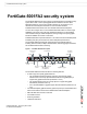
Security System Guide FortiGate-5001FA2 USB CONSOLE 1 2 3 4 5 6 7 8 STA IPM PWR ACC A detailed guide to the FortiGate-5001FA2 Security System. This FortiGate-5001FA2 Security System Guide describes FortiGate-5001FA2 hardware features, how to install the FortiGate-5001FA2 board in a FortiGate-5000 series chassis, how to configure the FortiGate-5001FA2 security system for your network, and contains troubleshooting information to help you diagnose and fix problems.
Warnings and cautions Only trained and qualified personnel should be allowed to install or maintain FortiGate-5000 series equipment. Read and comply with all warnings, cautions and notices in this document. • • • • • • • • • • • • ! CAUTION: Risk of Explosion if Battery is replaced by an Incorrect Type. Dispose of Used Batteries According to the Instructions.
Contents Contents Warnings and cautions ..................................................................................... 2 FortiGate-5001FA2 security system ................................. 5 Front panel LEDs and connectors ................................................................... 6 LEDs ............................................................................................................. 6 Connectors ..................................................................................
Contents For more information ...................................................... 33 Fortinet documentation .................................................................................. Fortinet Tools and Documentation CD........................................................ Fortinet Knowledge Center ........................................................................ Comments on Fortinet technical documentation ........................................
FortiGate-5001FA2 security system FortiGate-5001FA2 security system The FortiGate-5001FA2 security system is a high-performance FortiGate security system with a total of 8 front panel gigabit ethernet interfaces and two base backplane interfaces. Use the front panel interfaces for connections to your networks and the backplane interfaces for communication between FortiGate-5000 series boards over the FortiGate-5000 chassis backplane.
Front panel LEDs and connectors FortiGate-5001FA2 security system The FortiGate-5001FA2 board comes supplied with four optical or four copper SFP transceivers. Before you can connect FortiGate-5001FA2 interfaces 1 to 4, you must insert the SFP transceivers into the FortiGate-5001FA2 front panel cage slots numbered 1 to 4. The FortiGate-5001FA2 board ships with two RAM DIMMs installed on the FortiGate-5001FA2 circuit board.
FortiGate-5001FA2 security system Accelerated packet forwarding and policy enforcement Table 1: FortiGate-5001FA2 board LEDs (Continued) LED State Description 5, 6, Link 7, 8 LED Green The correct cable is inserted into this interface and the connected equipment has power. Flashing Network activity at this interface. Speed Green LED Amber Unlit The interface is connected at 1000 Mbps. The interface is connected at 100 Mbps. The interface is connected at 10 Mbps.
Base backplane gigabit communication FortiGate-5001FA2 security system • Session Oriented Traffic with long session lifetime, such as FTP sessions. Packet size does not affect performance for traffic with long session lifetime. For long sessions, processing that would otherwise be handled by the FortiGate-5001FA2 CPUs is off-loaded to the acceleration module. • Firewall and intrusion protection (IPS), when there is a reasonable percentage of P2P packets.
Hardware installation RAM DIMMs Hardware installation Before use, the FortiGate-5001FA2 board must be correctly inserted into an Advanced Telecommunications Computing Architecture (ACTA) chassis such as the FortiGate-5140, FortiGate-5050, or FortiGate-5020 chassis. Before inserting the board into a chassis you should make sure RAM DIMMS are installed and FortiGate-5001FA2 jumpers are set.
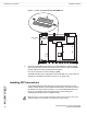
Installing SFP transceivers Hardware installation Figure 2: Location of FortiGate-5001FA2 RAM DIMM slots JP1 JP2 RAM DIMM slots JP3 Front Faceplate 3 Insert each RAM DIMM perpendicular to the RAM DIMM slots. Push the DIMM firmly into place using the minimum amount of force required. When the DIMM is properly seated, the socket guide posts click into place. Do not use excessive force when installing a DIMM. The RAM slots allow only one alignment of each RAM DIM.
Hardware installation Changing FortiGate-5001FA2 jumper settings You can install the following types of SFP transceivers for connectors 1, 2, 3, and 4: • optical SFP transceivers • • • SFP 1000Base-LX, SM module SFP 1000Base-SX, MM module (multimode) copper SFP transceivers • SFP 1000Base-T, SERDES version only (SGMII version not supported) To install SFP transceivers To complete this procedure, you need: ! • A FortiGate-5001FA2 board • Four SFP transceivers • An electrostatic discharge (ESD)
Changing FortiGate-5001FA2 jumper settings Hardware installation Normally, because the jumpers are factory set, you do not have to change them. However, if you are moving a FortiGate-5001FA2 from a FortiGate-5140 or FortiGate-5050 to a FortiGate-5020 or the reverse, you need to move the JP3 jumper. Also, if a new FortiGate-5001FA2 board does not function properly, you should check the JP3 jumper settings.
Hardware installation Inserting a FortiGate-5001FA2 board into a chassis To change or verify the JP3 jumper setting To complete this procedure, you need: ! • A FortiGate-5001FA2 board • A tool for moving jumpers (optional) • An electrostatic discharge (ESD) preventive wrist strap with connection cord Caution: FortiGate-5001FA2 boards must be protected from static discharge and physical shock. Only handle or work with FortiGate-5001FA2 boards at a static-free workstation.
Inserting a FortiGate-5001FA2 board into a chassis Hardware installation Figure 4: FortiGate-5001FA2 mounting components Closed Alignment Pin Alignment Pin Retention Screw Handle Retention Screw Lock Handle Lock Open Left Handle Power Switch Lock Switch Contact Before inserting the FortiGate-5001FA2 board in a chassis Before installing the FortiGate-5001FA2 board in a chassis you should verify that the RAM DIMMs are installed and the JP3 jumper is set correctly.
Hardware installation Inserting a FortiGate-5001FA2 board into a chassis ! Caution: FortiGate-5001FA2 boards must be protected from static discharge and physical shock. Only handle or work with FortiGate-5001FA2 boards at a static-free workstation. Always wear a grounded electrostatic discharge (ESD) preventive wrist strap when handling FortiGate-5001FA2 boards. 1 Attach the ESD wrist strap to your wrist and to an ESD socket or to a bare metal surface on the chassis or frame.
Inserting a FortiGate-5001FA2 board into a chassis 7 Hardware installation Turn both handles to their fully-closed positions. The handles should hook into the sides of the chassis slot. Closing the handles draws the FortiGate-5001FA2 board into place in the chassis slot and into contact with the chassis backplane. The FortiGate-5001FA2 front panel should be in contact with the chassis front panel. When the handles are fully-closed they lock into place.
Hardware installation Removing a FortiGate-5001FA2 board from a chassis Removing a FortiGate-5001FA2 board from a chassis The following procedure describes how to correctly use the FortiGate-5001FA2 mounting components shown in Figure 4 to remove a FortiGate-5001FA2 board from a FortiGate-5000 series chassis slot. To remove a FortiGate-5001FA2 board from a FortiGate-5000 series chassis FortiGate-5001FA2 boards are hot swappable.
Troubleshooting Hardware installation 5 Open the left and right handles to their fully open positions. Opening the handles slides the board a short distance out of the slot, disconnecting the board from the chassis backplane. The IPM LED turns blue. All other LEDs turn off. Alignment Pin Handle Handle Fully Open Open 6 Pull the board about half way out. All LEDs turn off. 7 Turn both handles to their fully-closed positions. When the handles are fully-closed they lock into place.
Hardware installation Troubleshooting Figure 5: Location of FortiGate-5001FA2 power switch Left Handle Power Switch Lock Switch Contact If the left handle is damaged or positioned incorrectly the FortiGate-5001FA2 board does not receive power and will not start up. Make sure the left handle is correctly aligned, fully inserted and locked. Sometimes you may have to make small adjustments to the handle to achieve contact with the switch.
Troubleshooting Hardware installation All chassis: Firmware problem If the FortiGate-5001FA2 board power switch is connected and the JP3 jumper and shelf manager are set as required, and the FortiGate-5001FA2 still does not start up, the problem could be with FortiOS. Connect to the FortiGate-5001FA2 console and try cycling the power to the board. If the BIOS starts up, interrupt the BIOS startup and install a new firmware image.
Quick Configuration Guide Registering your Fortinet product Quick Configuration Guide This section is a quick start guide to connecting and configuring a FortiGate-5001FA2 security system for your network. Before using this chapter, your FortiGate-5000 series or compatible ATCA chassis should be mounted and connected to your power system.
Planning the configuration Quick Configuration Guide NAT/Route mode In NAT/Route mode, the FortiGate-5001FA2 security system is visible to the networks that it is connected to. Each interface connected to a network must be configured with an IP address that is valid for that network. In many configurations, in NAT/Route mode all of the FortiGate interfaces are on different networks, and each network is on a separate subnet.
Quick Configuration Guide Choosing the configuration tool Figure 8: Example FortiGate-5001FA2 board operating in Transparent mode Internet 204.23.1.2 Gateway to public network 192.168.1.1 Transparent mode policies controlling traffic between internal and external networks. port2 USB CONSOLE 2 3 4 5 6 7 8 STA IPM PWR ACC Internal network 1 FortiGate-5001FA2 module Transparent mode policies in Transparent mode controlling traffic between internal and external networks.
Factory default settings Quick Configuration Guide Factory default settings The FortiGate-5001FA2 unit ships with a factory default configuration. The default configuration allows you to connect to and use the FortiGate-5001FA2 web-based manager to configure the FortiGate-5001FA2 board onto the network.
Quick Configuration Guide Configuring NAT/Route mode Using the web-based manager to configure NAT/Route mode 1 Connect port1 of the FortiGate-5001FA2 board to the same hub or switch as the computer you will use to configure the FortiGate board. Note: If you cannot connect to port1, see “Using the CLI to configure NAT/Route mode” on page 26. 2 Configure the management computer to be on the same subnet as the port1 interface of the FortiGate-5001FA2 board.
Configuring NAT/Route mode Quick Configuration Guide Using the CLI to configure NAT/Route mode 1 Use the serial cable supplied with your FortiGate-5001FA2 board to connect the FortiGate Console port to the management computer serial port. 2 Start a terminal emulation program (HyperTerminal) on the management computer. Use these settings: Baud Rate (bps) 9600, Data bits 8, Parity None, Stop bits 1, and Flow Control None. 3 At the Login: prompt, type admin and press Enter twice (no password required).
Quick Configuration Guide Configuring Transparent mode Configuring Transparent mode Use Table 7 to gather the information you need to customize Transparent mode settings. Table 7: Transparent mode settings Admin Administrator Password: Management IP IP: _____._____._____._____ Netmask: _____._____._____._____ The management IP address and netmask must be valid for the network where you will manage the FortiGate-5001FA2 unit. Default Gateway IP address: Default Route DNS Servers _____._____._____.
Upgrading FortiGate-5001FA2 firmware Quick Configuration Guide To configure the Primary and Secondary DNS server IP addresses 1 Go to System > Network > Options. 2 Enter the Primary and Secondary DNS IP addresses that you added to Table 7 on page 27 as required and select Apply. Using the CLI to configure Transparent mode 1 Use the serial cable supplied with your FortiGate-5001FA2 board to connect the FortiGate Console port to the management computer serial port.
Quick Configuration Guide Upgrading FortiGate-5001FA2 firmware 4 Under System Information > Firmware Version, select Update. 5 Type the path and filename of the firmware image file, or select Browse and locate the file. 6 Select OK. The FortiGate-5001FA2 board uploads the firmware image file, upgrades to the new firmware version, restarts, and displays the FortiGate login. This process takes a few minutes. 7 Log into the web-based manager.
FortiGate-5001FA2 base backplane data communication Quick Configuration Guide FortiGate-5001FA2 base backplane data communication You can configure the FortiGate-5001FA2 boards for data communications using the two FortiGate-5140, FortiGate-5050, or FortiGate-5020 chassis base backplane interfaces. Note: Different FortiGate-5000 series boards may use different names for the base backplane interfaces.
Quick Configuration Guide Powering off the FortiGate-5001FA2 board Figure 9: FortiGate-5001FA2 interface list with backplane interfaces enabled To enable base backplane data communication from the FortiGate-5001FA2 CLI From the FortiGate-5001FA2 board CLI you can use the following steps to enable base backplane data communication.
Powering off the FortiGate-5001FA2 board 32 Quick Configuration Guide FortiGate-5001FA2 Security System Guide 01-30000-0379-20080606
For more information Fortinet documentation For more information Support for your Fortinet product is available as online help from within the web-based manager, from the Tools and Documentation CD included with the product, on the Fortinet Technical Documentation web site, from the Fortinet Knowledge Center web site, as well as from Fortinet Technical Support.
© Copyright 2008 Fortinet, Inc. All rights reserved. No part of this publication including text, examples, diagrams or illustrations may be reproduced, transmitted, or translated in any form or by any means, electronic, mechanical, manual, optical or otherwise, for any purpose, without prior written permission of Fortinet, Inc.