FORTRESS EFLEX 5.4 kWh LITHIUM BATTERY INSTALLATION MANUAL SECURE YOUR ENERGY WITH FORTRESS LITHIUM BATTERY SYSTEMS Fortress battery systems utilize the industry’s most environmentally benign chemistry- Lithium Ferro Phosphate (LFP), which eliminates operating temperature constraints, toxic coolants, and the risk of thermal runaway and fire.
Rev. 1.8 General Information CAUTION! Do not combine Fortress Lithium Batteries with other brands or chemistries; Do not mix Fortress Lithium Batteries from different installations, clients, or job sites. CAUTION! Do not disassemble or modify the battery. If the battery housing is damaged, do not touch exposed contents.
Rev. 1.8 Table of Contents General Information ........................................................................................................................................... 2 Specifications .................................................................................................................................................... 5 Features ...................................................................................................................................................
Rev. 1.8 5. OPERATION ............................................................................................................................................... 25 5.1 Charging ................................................................................................................................................ 25 5.1.1 Please follow the following steps to use the charger to charge the battery: ...................................... 25 5.2 Discharging .........................................
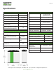
Rev. 1.8 Specifications Electrical Specifications Mechanical Specifications Nominal Voltage: 51.2V Nominal Capacity: 105AH Rated Capacity @ 0.5C (50A): <10 mΩ Efficiency (at 1C): Shipping Weight: 123lbs (56kg) 25.7x22.9x11.3 in (652x582x283mm) h Terminal Type: M8 Case Material: Aluminum 15 Enclosure Protection: <68A (3.5kW DC) 100A (5kW 60 Rate: Min) Maximum Surge Power Rate: 130A (6.
Rev. 1.8 Features . . 505 Keystone Rd, Southampton, PA 18966, USA (877) 497 6937 sales@fortresspower.com www.fortresspower.com 6 .
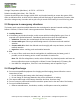
Rev. 1.8 Registering for the Fortress Power Warranty Fortress Power batteries come with a warranty that depends on charge parameters that define the depth of discharge (DoD) and other important variables. To ensure that Fortress Power is able to honor the warranty, please fill out the warranty letter (available at fortresspower.com/resources) as soon as the system is commissioned and send to sales@fortresspower.com.
Rev. 1.8 IMPORTANT NOTE: Circuit Breakers, Disconnects and Fuses should be employed throughout several points of a power storage and generation installation to effectively isolate and protect all components of the system to safeguard against faults, short circuits, polarity reversals or a failure of any component in the overall system.
Rev. 1.8 Storage Temperature (Min./Max.): 41°F/5°C – 95°F/35°C Relative Humidity (Min./Max.): 5%~75% RH Systems should be put into storage at 60% SOC and checked monthly to ensure the system SOC does not fall below 20%. At 20% SOC the battery will self-discharge in approximately 2 months. Also check the voltage every 3 months and recycle every 6 months if the battery is not use for long time. 2.
Rev. 1.8 2.5 Charging notes The battery must be transported, stored, and used in accordance with the instructions in this manual. If any of the following improper operations occur, this product will cancel the free warranty.
Rev. 1.8 2.6 System sizing Proper system sizing is vital to the health and proper operation of your battery. Using an inverter with a charging rate too close to the maximum recommended charge rate of the battery can cause the battery to malfunction due to safety mechanisms. Therefore, it is important to size the number of batteries correctly, depending on the power of the inverter. The table below lists some common inverters and the minimum number of eFlex batteries necessary to avoid malfunction.
Rev. 1.8 3. PRODUCT INTRODUCTION 3.1 Technical data Model eFlex 5.4 Total Energy(kWh) 5.4 Recommend Charge Current [A] 55 Max. Charge Current (Continuous) [A] 100 Recommend discharge current [A] <68 Max. Discharge Current (Continuous) [A] 100 Max Pulse Current for 5sec [A] 130 Capacity [Ah] 105 Voltage [V] 51.2 (48) Charging Temperature [F] 32~113 Discharging Temperature [F] 32~131 Dimension [LxWxH] [inches] 21.5x17.5x7.2 Packaging Dimension [inches] 25.7x22.9x11.
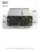
Rev. 1.8 3.2 Unboxing Check list The following items are included in the eFlex package: ❖ Battery ❖ 2 x Rubber terminal cap 1. Floor mount stabilization bracket 2. RJ45 adaptor and CAN resistor 3. RS485 Waterproof cable 4. CAN Bus terminator 1 2 3 . . 4 . 3.3 Accessories and Part Numbers The following accessories are available for purchase to mount the eFlex in several different ways. Please contact sales@fortresspower.com if interested in these kits. . .
Rev. 1.
Rev. 1.8 ➢ Positive and negative battery cables. It is recommended to install a 150A fuse between the bus bar and the battery. We recommend copper cables larger than AWG 2/0. The battery cables are not included. Please refer to the published Battery Cable Sizing Chart for the proper size, based on your system specification.
Rev. 1.8 4.3 Installation Considerations Although the eFlex is IP65 rated, if it is to be installed outdoors it is recommended that the installation location meet the following conditions: ✓ ✓ ✓ ✓ ✓ ✓ ✓ At minimum, the eFlex should be protected from inclement weather with a cover/enclosure. The area is completely waterproof. The floor is flat and level (Inclination < 15°). There are no flammable or explosive materials. The optimal ambient temperature is within the range from 59 ℉ to 95 ℉.
Rev. 1.8 Server Rack [Rack Unit] Useable Depth [Inch] eFlex Height [Inch] Quantity of eFlex 18U ≥24 7.20 4 21U ≥24 7.20 4 27U ≥24 7.20 6 35U ≥24 7.20 8 40U ≥24 7.20 9 45U ≥24 7.20 10 Please follow the following steps to mount the eFlex in a 19” server rack. 1. Ensure your shelf mounts are properly secured 2. Optional: If you choose to use the stabilizing brackets, affix those to the eFlex using T-slot bolts 3. Slide the eFlex onto the shelf mount 4.
Rev. 1.8 4.4.2. Mounting the battery pack to a wall The eFlex 5.4 can be easily wall-mounted using our custom T-slot brackets. The wall-mounting brackets are sold separately. Please ensure the wall and mounting hardware can handle the weight of the batteries. 1. Line up the top bracket on the wall. a. Mark the desired placement using a level to ensure the bracket is horizontal b. Affix the mounting bracket into the wall 2. Using the T-slot screws, fix the male brackets onto the slots in the battery 3.
Rev. 1.8 4.4.3 Floor standing installation The eFlex 5.4 can be floor-mounted in several orientations to best suit your application. When determining the battery orientation for floor-mounting, it is important to note that the orientation depicted to the right, with the terminals closest to the floor is NOT recommended. When mounting the eFlex to the floor, use the included mounting brackets to prevent the battery from tipping over. 1. Gently place the eFlex on the floor in the preferred orientation 2.
Rev. 1.8 inverter/charge controller. Below is a sketch of the communication between paralleled batteries. If you need to make a communication cable, please refer to the pinout diagram for an RJ45 cable below. CAUTION! Please check with Fortress Power to see if you can use the CAN comm. port to connect the battery to your charge controller or battery-based inverter. . . 505 Keystone Rd, Southampton, PA 18966, USA (877) 497 6937 sales@fortresspower.com www.fortresspower.com 20 .
Rev. 1.8 4.4.6 Using a single eFlex battery pack Installation procedure for a single eFlex battery 1. Put the inverter breaker/on and off switch into “OFF” position (if there is any) 2. Connect the positive and negative terminals to the inverter 3. Turn on eFlex unit by pressing the eFlex power button and waiting ~10sec until LED diagnostic is complete. 4.
Rev. 1.8 4.4.7 Parallel Connection of >1 eFlex battery For a maximum battery bank size of 81KWH, up to 15 eFlex batteries can be connected in parallel. All wires should be an appropriate gauge and constructed to handle the loads that will be placed upon them. Heavy gauge, fine strand copper wire is the industry standard due to its stability, flexibility, efficiency and overall quality. A qualified installer should understand this and must adhere to the industry standard and published electrical guidelines.
Rev. 1.8 Please follow this procedure to commission eFlex batteries in parallel: 1. Turn OFF all equipment in the system 2. Connect the positive and negative common bus to the inverter. 3. Prepare and connect communication cable. Each unit comes with one RJ45 cable. If the cable is missing, please make sure the cable you purchase on the market meets the following standards. Please note that a standard RS485 cable is used. Please see section 4.4.5 for the pinout information.
Rev. 1.8 KEY POINTS SUMMARY: 1. Each Fortress Lithium Battery contains circuitry that protects the Lithium Ferro Phosphate cells from overcharging, over-discharging, and excessive load amperage. If the values specified are exceeded, the battery will enter a protective shut down state. In some cases, this may result in the need to reinitialize an inverter charger or other pieces of equipment in the installation.
Rev. 1.8 5. OPERATION 5.1 Charging Never attempt to charge a battery without first reviewing and understanding the instructions for the charger being used. Only use a Fortress Power Approved Lithium Ferro Phosphate (LFP) charger if ancillary charging is required before installation, testing or troubleshooting. Failure to use a Fortress Power approved LFP charger may damage the battery and void the warranty Temperature Table of Charging: Ambient Temp Max Charge Current 0℃<T≤5℃ 0.1C 5℃<T≤10℃ 0.
Rev. 1.8 5.3 Parameter set up guide for Charger/Inverter Before commissioning the energy storage system, the appropriate controller and inverter settings must be programmed per the manufacturer’s recommendations. Consult the manufacturer’s manuals and/or access technical support (Darfon, Schneider, Outback, SMA, Sol-Ark, Magnum, Outback).
Rev. 1.8 6. DIAGNOSTIC/INTERFACE GUIDE The eFlex has six LEDs on the front face allowing the user to decode the state of the battery as well as any important messages from the BMS. When the eFlex is turned on, each LED will also turn on and display a LED mode. The red “BMS” light will turn on during start-up diagnostic as well as when there is a communication error between batteries. If the problem persists, please contact Fortress Power tech support. In normal operation, the “RUN” LED light will be on.
Rev. 1.8 PLEASE CONTACT US FOR TECHNICAL SUPPORT Fortress Power, LLC 505 Keystone Road, Southampton, Pennsylvania, 18966 877.497.6937 techsupport@fortresspower.com www.FortressPower.com . . 505 Keystone Rd, Southampton, PA 18966, USA (877) 497 6937 sales@fortresspower.com www.fortresspower.com 28 .