COMPANY NAME ANNUAL REPORT 01 COMPANY NAME Company Activity
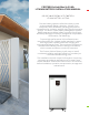
FORTRESS eVault Max 18.5 kWh LITHIUM BATTERY INSTALLATION MANUAL SECURE YOUR ENERGY WITH FORTRESS LITHIUM BATTERY SYSTEMS Fortress battery systems utilize the industry’s most environmentally benign chemistry- Lithium Ferro Phosphate, which eliminates operating temperature constraints, toxic coolants, and the risk of thermal runaway and fire.
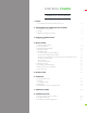
FORTRESS POWER TABLE OF CONTENTS 1. SAFETY 1.1 General Safety Precautions and Safety Instructions 6 2. TRANSPORTATION, HANDLING AND STORAGE 2.1 Transportation and Handling 2.2 Storage 2.3 Response to Emergency Situations 7 7 7 3. PRODUCT INTRODUCTIONS 3.1 Technical Data 8 4. INSTALLATION 4.1 Environment Requirement 4.1 Tools and Material 4.3 Inspection Before Installation 4.4 Installation Location 4.5 Installation Steps 4.5.1 Mounting and Securing the Battery 4.5.
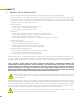
1. SAFETY 1.1 GENERAL SAFETY PRECAUTIONS • All types of breakdown of the product may lead to a leakage of electrolyte or flammable gas. • During installation of the battery, the utility grid, solar input must be disconnected from the Battery Pack wiring. Wiring must be carried out by qualified personnel. Battery Pack is not user serviceable. High voltage or current is present in the device. The electronics inside the Battery Pack are vulnerable to electrostatic discharge.
CAUTION! Do not disassemble or modify the battery. If the battery housing is damaged, do not touch exposed contents. 2. TRANSPORTATION, HANDELING AND STORAGE 2.
3. PRODUCT INTRODUCTION 3.1 TECHNICAL DATA MODEL EVAULT MAX 18.5 Total Energy(kWh) 18.5 Recommend Charge Current 100 Max. Charge Current (Continuous) [A] 170 Max. Discharge Current Continuous) [A] 180 Max Pulse Current for 10sec [A] 200 Capacity [Ah] 360 Voltage [V] 51.2 (48) Charging Temperature [F] 32~113 Discharging Temperature [F] 32~140 Dimension [WxDxH] in Inch 20.3 x 20.3 x 42.
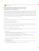
4.1 ENVIRONMENT REQUIREMENT Application scenarios Residence Operating Environment Indoor and place away from strong electromagnetic radiation Operating Temperature -10~55°C (14~131°F) IP grade IP54 Storage Temperature Short time(≤1month): -20~45°C (-4~110°F) Long time (≥1month): 15~35°C (59~95°F) Operating Humidity 0 ~ 85% Max charge/discharge current Vs. Altitude 180A@≤2,000m 162A@2,000m~4,000m Case Ground requirement Use at least 6mm² copper wire with the resistor≤1Ω. 4.
4.
4.5.3 Connecting the battery to the Charge Controller and/or Hybrid Inverter The battery terminals are positioned under the top cover. Please use the screw driver to take the screws along the top cover off. Please make sure the breaker near the terminal is in the OFF position. Please install the positive cable first and the negative cable second. Please do not cross the positive and negative terminals; also, ensure the terminals are not connected to any metal mounting, fixture, or body part.
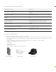
4.5.4 Battery Communications Fortress eVault Max 18.5 has a self-managed Battery Management System (BMS). No communication is required between a battery-based inverter and the eVault Max 18.5 to operate the system. The Communication Box has five ports next to the battery breaker (refer to communication box picture below). Those ports are designed to support Inverter RS 485 and CAN communication, battery parallel communication (see section 4.4.6.) and USB Logging.
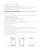
The Storage Capacity and total available Amperage are increased by the parallel arrangement. The following illustration shows how to connect multiple batteries in parallel. Please note the overall Voltage is not changed. The available Amperage from the system has been doubled. Parallel wiring CAUTION! For parallel connecting: Maintain identical wire length and wire construction from each Fortress Power Battery terminal to the common bus.
2. Confirm the Battery DC circuit breaker is in the “OFF” position. 3. Wire each battery’s power bus to inverter. Wire inverter’s cable to PV, Grid and Load. 4. Use the CAT5/6 cables to connect the batteries’ COM Parallel port, as illustrated in the chart below. Ensure communication matching resistor of two terminal is set as 120Ω, while the others are set to OFF. 5. Press the button on the front of each battery for 3+ seconds one by one, until all batteries start up. 6.
9. Turn ON the inverter breaker, then turn ON all battery DC breakers, and then press the button of master battery (Battery ID 1) for 6+ seconds to turn off. Finally, press the button on the master battery for 3+ seconds to start the automatic PARALLEL PROCESS: The master battery orders the lowest voltage battery of the whole system to pre-charge and turn on relay, and request charge current from inverter. As the battery voltage increases, batteries join parallel circuit one by one.
KEY POINTS SUMMARY: 1. Each Fortress Lithium Battery contains circuitry that protects the Lithium Ferro Phosphate cells from overcharging, over-discharging, and excessive load amperage. If the values specified are exceeded, the battery will enter a protective shut down state. In some cases, this may result in the need to re- initialize an inverter charger or other pieces of equipment in the installation.
6. OPERATING 6.1 OPERATING ENVIRONMENT See “3.1 Technical Data” Table on page 5 6.2 CHARGING Never attempt to charge a battery without first reviewing and understanding the instructions for the charger being used. Only use a Fortress Power Approved Lithium Ferro Phosphate (LFP) charger if ancillary charging is required before installation, testing or troubleshooting. Failure to use a Fortress Power approved LFP charger will damage the battery and void the warranty.
Charger/Inverter configuration recommendation for best Performance: The Battery Parameter Setting Guides with SMA, Sol-Ark, Schneider and Outback Inverters/Chargers are available to download on www.fortresspower.
8. TROUBLESHOOTING 8.1 GENERAL SYMPTOM-SOLUTION SITUATIONS SYMPTOM Unit voltage at terminals is extremely low or is bleeding down (steep decline) SOLUTION Unit’s BMS is in Protection Mode. There are two possible solutions. 1. Use a 48V charger to trickle charge the battery in order activate the BMS 2. Use the BMS-to-Computer Adapter Cable in conjunction with the BMS Tool Software on a Windows Computer to forcibly reset the Charge/Discharge Relays. Contact Fortress Power Tech Support.
8.2 LCD DISPLAY WARNINGS ERROR MEANING over high voltage protection over low voltage protection Discharge over-temp protection, charge over-temp protection, environmental over-temp protection Discharge low-temp protection, charging low-temp protection, environmental low-temp protection Discharge over current protection, charge over current protection Short circuit protection 8.
RUNNING STATE STATUS RUN ALM · - lower the power used · disconnect the battery and turn it on after lowering the power - start charging · charging activation Charge over current alarm Charge over current protection Discharge total low-voltage alarm Discharge total low-voltage protection Discharge cell low-voltage alarm Discharge cell low-voltage protection Discharge over current alarm · Discharge over current protection - Temperature charge overtemperature alarm · Temperatu
RUNNING STATE STATUS RUN ALM Temperature environment over temperature alarm · - reduce the environment temperature Temperature environment over temperature protection - reduce the environment temperature Temperature environment low temperature alarm · · - improve the environment temperature Temperature environment low temperature protection - · improve the environment temperature PLEASE CONTACT US FOR TECHNICAL SUPPORT Fortress Power, LLC 505 Keystone Road, Southampton, Pennsylvania,