FORTRESS POWER 1 V4.
EVAULT MAX INSTALLATION MANUAL 2 V4.
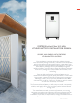
FORTRESS eVault Max 18.5 kWh LITHIUM BATTERY INSTALLATION MANUAL SECURE YOUR ENERGY WITH FORTRESS LITHIUM BATTERY SYSTEMS Fortress battery systems utilize the industry’s most environmentally benign chemistry- Lithium Ferro Phosphate, which eliminates operating temperature constraints, toxic coolants, and the risk of thermal runawayand fire.
V4.
FORTRESS POWER TABLE OF CONTENTS 1. SAFETY 1.1 General Safety Precautions and Safety Instructions 6 2. TRANSPORTATION, HANDLING AND STORAGE 2.1 Transportation and Handling 7 2.2 Storage 7 2.3 Response to Emergency Situations 7 3. PRODUCT INTRODUCTIONS 3.1 Technical Data 8 4. INSTALLATION 4.1 Environmental Requirements 4.2 Tools and Materials 9 9 4.3 Inspection Before Installation 9 4.4 Installation Location 10 4.5 Mechanical Installation Steps 10 4.5.1 Mounting and Securing the Battery 4.
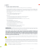
1. SAFETY 1.1 GENERAL SAFETY PRECAUTIONS • All types of damage to the product may lead to a leakage of electrolyte or flammable gas. • During installation of the battery, the utility grid, solar input must be disconnected from the Battery Pack wiring. Wiring must be carried out by qualified personnel. The battery pack contains no user serviceable parts. High voltage or current is present in the device. The electronics inside the Battery Pack are vulnerable to electrostatic discharge.
CAUTION! Do not disassemble or modify the battery. If the battery housing is damaged, do not touch exposed contents. 2. TRANSPORTATION, HANDELING AND STORAGE 2.
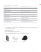
3. PRODUCT INTRODUCTION 3.1 TECHNICAL DATA Electrical Total Energy (kWh) 18.5 Recommend Charge Current 150 Max. Charge Current (Continuous) [A] 180 Max. Discharge Current Continuous) [A] 180 Max Pulse Current for 10sec [A] 200 Capacity [Ah] 360 Voltage [V] 51.2 (48V Nom) Charging Temperature [F] 32°F ~ 120°F (0°C ~ 49°C) Discharging Temperature [F] 14°F ~ 120°F (-10°C ~ 49°C) Circuit Breaker/Disconnecting Means 250 A Battery Efficiency >98% Mechanical Dimension [WxDxH in] 20.
4.1 ENVIRONMENTAL REQUIREMENTS Application scenarios Residential/Small Commercial Operating Environment Indoor and away from strong electromagnetic radiation Operating Temperature 14°F ~ 120°F (-10°C ~ 49°C) IP grade IP55 Storage Temperature Short Duration (≤1month): -20~45°C (-4~110°F) Long Duration (≥1month): 5~35°C (41~95°F) Operating Humidity 0 ~ 85% non-condensing Max charge/discharge current vs.
4.
4.5.3 Connecting the battery to the Charge Controller and/or Hybrid Inverter The battery terminals are positioned under the top cover. To open the cover, slide the raised latch to the right, the handle will then pop up, rotate it counterclockwise 90° and lift the lid to the open position. Note: the lid does not have a mechanism to keep it from shutting so be sure to open it past 90° or use an object to hold it open.
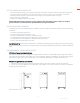
4.5.4 Battery Communications The eVault Max 18.5 has a self-contained Battery Management System (BMS). No communication is required between a battery-based inverter and the eVault Max 18.5 to operate the system, though closed loop communication is recommended to improve battery and inverter performance. The Communication Box has five ports next to the battery breaker (refer to communication box picture below).
When installing multiple inverters with one or more eVault Max 18.5, please turn the first inverter on then use the following the steps, then power up the remaining inverters. 4.5.7 Parallel eVault Max Units eVault Max units with the same capacity may be connected in parallel in configurations of up to 20, this is the maximum number allowed for consistent and robust operation. Quantities greater than this will require consultation with Fortress Power.
eVault Max Communication Interface Details Note: The Inverter CAN and RS485 portsare optional and only one is used at a time for closed loop inverter communications. The battery RS484 port is used when the inverter requires a MODBUS interface such as on the Sol-Ark 12, 8, & 5k, as well as the Schneider XW Plus. Inverter CAN INVERTER CAN PORT COM_Parallel RS485 BATTERY COM_PARALLEL INVERTER RS485 PORT Pin No. Definition Pin No. Definition Pin No. Definition 1. INVERTER_CANH 1. NC 1.
Procedure to Parallel eVault Max Batteries 4.6 COMMUNICATION CONNECTIONS 1. Confirm that each battery DC circuit breaker is in the “OFF” position. 2. Wire each battery to your systems battery combiner. Connect the applicable AC and DC wiring on the inverter side of the system. 3. Connect the first eVault COM_Parallel OUT to the input of the next eVault’s IN port. Each unit comes with one RJ45 cable for this purpose.
4 Victron CANBUS 5 Schneider MODBUS 6 Reserved 7 Reserved 8 Reserved 8. Use a CAT5/5e or greater cable to connect the CAN or RS-485 port of master battery (the Battery ID set as 1) to inverter communication port. 9. Turn ON the inverter breaker, then turn ON all battery DC breakers, and then press the button of master battery (Battery ID 1) for 8+ seconds to turn off. Finally, press the button on the master battery for 3+ seconds to start the automatic PARALLEL PROCESS. 10.
4.8 LCD SCREEN AND ALARM WARNINGS The LCD display on the front of eVault Max provides Battery Voltage (V), Charging and Discharging Current (A), State of Charge (SOC), as well as Charging and Discharging Power Output (kW). Please note, when the battery is charging, the Current (A) will show a negative value, while during the discharging the Current (A) is positive. The green light (RUN) indicates system is running properly.
4.9 FINAL CONNECTION OF THE INSTALLATION Final installation and operation guidelines will be dictated by your Electrician and Installer based on the overall properties of and procedures for the equipment in your installation and any code requirements that apply to your region. Fortress Power technicians and sales staff are available to provide any additional information onthe eVault Max as needed.
6. OPERATING 6.1 OPERATING ENVIRONMENT See “3.1 Technical Data” Table 6.2 CHARGING Never attempt to charge a battery without first reviewing and understanding the instructions for the charger being used. Only use a Fortress Power Approved Lithium Ferro Phosphate (LFP) charger if ancillary charging is required before installation, testing or troubleshooting. Failure to use a Fortress Power approved LFP charger will damage the battery and void the warranty.
INVERTER/CHARGER CONFIGURATION : A PDF manual with settings for SMA, Sol-Ark, Schneider, Outback and other Inverters/Chargers is available for download at our website. For a detailed breakdown of operating conditions and how they can affect battery life and the 10 (5) year battery warranty please see the eVault Max Warranty document on our website. CAUTION! Do Not Operate the eVault Max at an average temperature exceeding 30°C / 86°F over the life of the battery. 7.
8. TROUBLESHOOTING 8.1 GENERAL TROUBLESHOOTING GUIDE ISSUE Unit voltage at terminals is extremely low or is bleeding down (steep decline) SOLUTION Unit’s BMS is in Protection Mode. There are two possible solutions. 1. Use a 48V charger to trickle charge the battery in order activate the BMS 2. Use the BMS-to-Computer Adapter Cable in conjunction with the BMS Tool Software on a Windows Computer to forcibly reset the Charge/Discharge Relays. Contact Fortress Power Tech Support.
8.2 LCD DISPLAY WARNINGS ERROR LIST over high voltage protection over low voltage protection Discharge over-temp protection, charge over-temp protection, environmental over-temp protection Discharge low-temp protection, charging low-temp protection, environmental low-temp protection Discharge over current protection, charge over current protection Short circuit protection 8.
RUNNING STATE STATUS RUN ALM · - lower the power used · disconnect the battery and turn it on after lowering the power - start charging · charging activation Charge over current alarm Charge over current protection Discharge total low-voltage alarm Discharge total low-voltage protection Discharge cell low-voltage alarm Discharge cell low-voltage protection Discharge over current alarm · Discharge over current protection - Temperature charge overtemperature alarm · Temperatu
RUNNING STATE STATUS RUN ALM Temperature environment over temperature alarm · - reduce the environment temperature Temperature environment over temperature protection - reduce the environment temperature Temperature environment low temperature alarm · · - improve the environment temperature Temperature environment low temperature protection - · improve the environment temperature DISPLAY SOLUTION 24 V4.
About Fortress Power Our mission is to provide compact, user-friendly, and affordable energy storage solutions using the latest technology for all homes and businesses. Fortress solar energy storage batteries can easily integrate with new and existing PV systems and work with a wide range of existing inverter and charge controller manufacturers for ease in system design. Contact Information Address: Corporate Headquarters 505 Keystone Rd Suite D Southampton, PA 18966 USA Website: www.fortresspower.