
Schneider Electric Integration Guide

Rev 2.2 02-10-22
Fortress Power – Schneider XW Pro Inverter Guide
505 Keystone Rd, Southampton, PA 18966 . (877) 497 6937. sales@fortresspower.com . Fortresspower.com
3
2. Communication Settings
Step 1: Hardware Integration
eFlex 5.4kWh
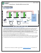
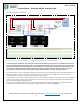
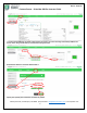
IMAGE 2.1: EXAMPLE OF COMPLETE HARDWARE SETUP BETWEEN 3 EFLEX 5.4KWH AND SCHNEIDER XW PRO. THE SAME CONFIGURATION
APPLIES TO INSTALLATIONS OF 1 BATTERY TO 15 BATTERIES CONNECTED IN PARALLEL
***Important! Before paralleling each battery, make sure the voltage difference between them is less than 0.5v from one
another. Pairing batteries with voltages above 0.5v may damage parts of your battery due to over surge current. If the
battery/ies have voltage differences use the inverter or charge controller to charge the battery/ies up to the desired voltage.
Otherwise, place the terminator in one of the communication ports and the communication cable in another.
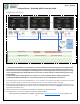
1. While batteries are off, connect the communication cables from one battery to another (RS485 ports are common) and end
communication with terminator on battery 3 as referred on Image 2.1. Insert the remaining cable from battery 1 to the Rj45
Pinout Converter to terminate the CAN communication from battery to battery.
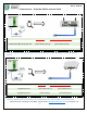
2. Plug a Format B Ethernet Cable (not included) to the other side of the Rj45 Pinout Converter.
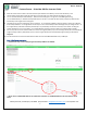
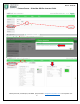
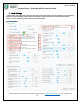
3. Cut and strip the end of the Format B cable and connect wire 7 (brown/white) to port 9 of the Insight Home (18 on the Gateway
& Insight Facility) and wire 8 (brown) to port 11 of the Insight Home (20 on the Gateway) as described in Image 2.2 & Image 2.3
4. Turn battery #1 first and wait 5 seconds, then proceed turning battery #2 on, wait 5 seconds, finalize turning battery #3 on.
1
2
3