
User Guide
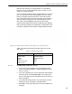


Table Of Contents
- Front
- Introduction
- Bridge GUI and Administrative Access
- 2.1 Bridge GUI
- 2.2 Administrative Accounts and Access
- 2.2.1 Global Administrator Settings
- 2.2.2 Individual Administrator Accounts
- 2.2.2.1 Administrator User Names
- 2.2.2.2 Account Administrative State
- 2.2.2.3 Administrative Role
- 2.2.2.4 Administrator Audit Requirement
- 2.2.2.5 Administrator Full Name and Description
- 2.2.2.6 Administrator Interface Permissions
- 2.2.2.7 Administrator Passwords and Password Controls
- 2.2.2.8 Adding Administrative Accounts
- 2.2.2.9 Editing Administrative Accounts
- 2.2.2.10 Deleting Administrative Accounts
- 2.2.2.11 Changing Administrative Passwords
- 2.2.2.12 Unlocking Administrator Accounts
- 2.2.3 Administrator IP Address Access Control
- 2.2.4 SNMP Administration
- Network and Radio Configuration
- 3.1 Network Interfaces
- 3.2 Bridging Configuration
- 3.3 Radio Settings
- 3.3.1 Advanced Global Radio Settings
- 3.3.2 Individual Radio Settings
- 3.3.3 DFS Operation and Channel Exclusion
- 3.3.4 Radio BSS Settings
- 3.3.4.1 BSS Administrative State and Name
- 3.3.4.2 BSS SSID and Advertise SSID
- 3.3.4.3 Wireless Bridge and Minimum RSS
- 3.3.4.4 User Cost Offset and FastPath Mesh Mode
- 3.3.4.5 BSS Switching Mode and Default VLAN ID
- 3.3.4.6 BSS G Band Only Setting
- 3.3.4.7 BSS WMM Setting
- 3.3.4.8 BSS DTIM Period
- 3.3.4.9 BSS RTS and Fragmentation Thresholds
- 3.3.4.10 BSS Unicast Rate Mode and Maximum Rate
- 3.3.4.11 BSS Multicast Rate
- 3.3.4.12 BSS Description
- 3.3.4.13 BSS Fortress Security Setting
- 3.3.4.14 BSS Wi-Fi Security Settings
- 3.3.4.15 Configuring a Radio BSS
- 3.3.5 ES210 Bridge STA Settings and Operation
- 3.3.5.1 Station Administrative State
- 3.3.5.2 Station Name and Description
- 3.3.5.3 Station SSID
- 3.3.5.4 Station BSSID
- 3.3.5.5 Station WMM
- 3.3.5.6 Station Fragmentation and RTS Thresholds
- 3.3.5.7 Station Unicast Rate Mode and Maximum Rate
- 3.3.5.8 Station Multicast Rate
- 3.3.5.9 Station Fortress Security Status
- 3.3.5.10 Station Wi-Fi Security Settings
- 3.3.5.11 Establishing an ES210 Bridge STA Interface Connection
- 3.3.5.12 Editing or Deleting the ES210 Bridge STA Interface
- 3.3.5.13 Enabling and Disabling ES210 Bridge Station Mode
- 3.4 Basic Network Settings Configuration
- 3.5 Location or GPS Configuration
- 3.6 DHCP and DNS Services
- 3.7 Ethernet Interface Settings
- 3.7.1 Port Administrative State
- 3.7.2 Port Speed and Duplex Settings
- 3.7.3 Port FastPath Mesh Mode and User Cost Offset
- 3.7.4 Port Fortress Security
- 3.7.5 Port 802.1X Authentication
- 3.7.6 Port Default VLAN ID and Port Switching Mode
- 3.7.7 Port QoS Setting
- 3.7.8 Port Power over Ethernet
- 3.7.9 Configuring Ethernet Ports
- 3.8 QoS Implementation
- 3.9 VLANs Implementation
- 3.10 ES210 Bridge Serial Port Settings
- Security, Access, and Auditing Configuration
- 4.1 Fortress Security
- 4.1.1 Operating Mode
- 4.1.2 MSP Encryption Algorithm
- 4.1.3 MSP Key Establishment
- 4.1.4 MSP Re-Key Interval
- 4.1.5 Access to the Bridge GUI
- 4.1.6 Secure Shell Access to the Bridge CLI
- 4.1.7 Blackout Mode
- 4.1.8 FIPS Self-Test Settings
- 4.1.9 Encrypted Data Compression
- 4.1.10 Encrypted Interface Cleartext Traffic
- 4.1.11 Encrypted Interface Management Access
- 4.1.12 Guest Management
- 4.1.13 Cached Authentication Credentials
- 4.1.14 Fortress Beacon Interval
- 4.1.15 Global Client and Host Idle Timeouts
- 4.1.16 Changing Basic Security Settings:
- 4.1.17 Fortress Access ID
- 4.2 Internet Protocol Security
- 4.3 Authentication Services
- 4.3.1 Authentication Server Settings
- 4.3.2 The Local Authentication Server
- 4.3.2.1 Local Authentication Server State
- 4.3.2.2 Local Authentication Server Port and Shared Key
- 4.3.2.3 Local Authentication Server Priority
- 4.3.2.4 Local Authentication Server Max Retries and Retry Interval
- 4.3.2.5 Local Authentication Server Default Idle and Session Timeouts
- 4.3.2.6 Local Authentication Server Global Device, User and Administrator Settings
- 4.3.2.7 Local 802.1X Authentication Settings
- 4.3.2.8 Configuring the Local RADIUS Server
- 4.3.3 Local User and Device Authentication
- 4.4 Local Session and Idle Timeouts
- 4.5 ACLs and Cleartext Devices
- 4.6 Remote Audit Logging
- 4.1 Fortress Security
- System and Network Monitoring
- System and Network Maintenance
- Index
- Glossary

Bridge GUI Guide: Network Configuration
111
you configure for each VLAN that the Bridge secures. The
routable VLAN IDs received on clear interfaces are translated,
according to the routing map, into non-routable IDs and
transmitted on an encrypted interface, and vice versa (non-
routable VLAN IDs received on encrypted interfaces are
translated into routable IDs and transmitted on a clear
interface).
NOTE: VLAN
translation occurs
only on traffic received
in one zone (clear or en-
crypted) and transmit-
ted in the other zone.
VLAN IDs passed from
one interface to another
within the same zone
are not translated.
Routable VLAN IDs must therefore be part of a trunk in the
clear zone, and
Non-Routable VLAN IDs must be part of a trunk
on an encrypted port. VLAN IDs that are passed within the
same zone do not have to be present in the VLAN routing map.
The Bridge can support up to 24 VLANs in translate mode:
each translation requires two VLAN IDs, for a maximum of 48
VLAN IDs on the VLAN translation map.
If the Bridge's encrypted and clear interfaces reside on the
same OSI layer-2 switch, use
Translate mode.
3.9.2 Native VLAN
The native VLAN can be used as management VLAN, allowing
you to use tagged traffic to manage the Bridge.
On an interface with a VLAN
Switching Mode of Trunk, you can
access the Bridge’s management interface only with packets
tagged with the Bridge’s
Native VLAN ID. You can manage the
Bridge on an interface with a VLAN
Switching Mode of Access
only with untagged packets and only when the interface’s
Default VLAN ID matches the Bridge’s global Native VLAN ID.
You can reconfigure the Bridge to use a native VLAN ID other
than 1 (the default), which automatically adds the new number
to the Bridge’s VLAN ID table (described in Section 3.9.3). If
the new ID is already present on the VLAN ID table, it will
simply be selected as the
Native VLAN ID.
VLAN functions are available only in Advanced View.
To configure basic VLAN settings
1 Log on to the Bridge GUI through an Administrator-level
account and select
ADVANCED VIEW in the upper right corner
of the page, then
Configure -> VLAN from the menu on the
left.
2 In the VLAN Settings frame, enter new values for those
settings you want to configure (described above).
3 Click APPLY in the upper right of the screen (or RESET
screen settings to cancel your changes).
4 If you selected a VLAN Mode of Normal or Translate, refer to
Section 3.9.3 to configure additional VLANs. For
Translate
mode, refer to Section 3.9.4 to create VLAN map records.
You cannot configure VLANs when
STP or FastPath Mesh is
selected as the Bridge’s
Bridging Mode (refer to Section 3.2).