QA review draft1 ES2440 High-Capacity Infrastructure Mesh Point Hardware Guide www.fortresstech.
QA review draft1 ES2440 Hardware Guide Fortress ES2440 High-Capacity Infrastructure Mesh Point [rev.1] 009-00045-00r1 Copyright © 2011 Fortress Technologies, Inc. All rights reserved. This document contains proprietary information protected by copyright.
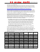
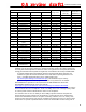
QA review draft1 ES2440 Hardware Guide IMPORTANT FCC INFORMATION The Federal Communications Commission has released Office of Engineering and Technology Laboratory Division Knowledge Database (KDB) 44399, which refines the definition of Dynamic Frequency Selection (DFS) support. Since this device has the ability to use frequencies covered by DFS, KDB 443999 must be followed. It is published in full on the FCC web site: https://apps.fcc.gov/oetcf/kdb/forms/FTSSearchResultPage.
QA review draft1 TDWR Location Information STATE CITY LONGITUDE LATITUDE FREQUENCY ES2440 Hardware Guide TERRAIN ELEVATION (MSL) [ft] ANTENNA HEIGHT ABOVE TERRAIN [ft] MA BOSTON W 070 56 01 N 42 09 30 5610 MHz 151 113 MD BRANDYWINE W 076 50 42 N 38 41 43 5635 MHz 233 113 MD BENFIELD W 076 37 48 N 39 05 23 5645 MHz 184 113 MD CLINTON W 076 57 43 N 38 45 32 5615 MHz 249 97 MI DETROIT W 083 30 54 N 42 06 40 5615 MHz 656 113 MN MINNEAPOLIS W 092 55 58 N 44 52 17 56
QA review draft1 ES2440 Hardware Guide license should NOT be considered to be compliant with FCC regulatory requirements. Please contact Fortress with questions about these special licences. Only software that has been signed by Fortress using the Fortress private key can be loaded onto a Fortress device, thus insuring that no software other than that which is controlled and signed by Fortress can by loaded onto the device.
QA review draft1 ES2440 Hardware Guide (MEANING THEY HAVE PRIORITY) OF 5250-5350 MHZ AND 5650-5850 MHZ AND THESE RADARS COULD CAUSE INTERFERENCE AND/OR DAMAGE TO LE-LAN DEVICES. ICES-003 STATEMENT: THIS CLASS B DIGITAL APPARATUS COMPLIES WITH CANADIAN ICES-003. CET APPAREIL NUMÉRIQUE DE LA CLASSE B EST CONFORME À LA NORME NMB-003 DU CANADA. THIS DEVICE HAS BEEN DESIGNED TO OPERATE WITH THE ANTENNAS HAVING A MAXIMUM GAIN OF 9 DB.
QA review draft1 ES2440 Hardware Guide: Table of Contents Table of Contents 1 Overview 1 This Document . . . . . . . . . . . . . . . . . . . . . . . . . . . . . . . . . . . . . . . . .1 Related Documents . . . . . . . . . . . . . . . . . . . . . . . . . . . . . . . . . . . . . . . . . . . 1 The ES2440 . . . . . . . . . . . . . . . . . . . . . . . . . . . . . . . . . . . . . . . . . . .2 Hardware Models . . . . . . . . . . . . . . . . . . . . . . . . . . . . . . . . . . . . . . . . . . . . .
QA review draft1 ES2440 Hardware Guide: Table of Contents 4 Specifications 12 Hardware Specifications . . . . . . . . . . . . . . . . . . . . . . . . . . . . . . . . . 12 Physical Specifications . . . . . . . . . . . . . . . . . . . . . . . . . . . . . . . . . . . . . . . . 12 Environmental Specifications . . . . . . . . . . . . . . . . . . . . . . . . . . . . . . . . . . . 12 Compliance and Standards . . . . . . . . . . . . . . . . . . . . . . . . . . . . . . . . . . . .
QA review draft1 ES2440 Hardware Guide: Overview Chapter 1 Overview 1.1 This Document This user guide covers preparing and installing the Fortress ES2440 High-Capacity Infrastructure Mesh Point hardware. It also describes the LED indicators and recessed button operation and provides specifications. Other Fortress hardware devices are covered in separate hardware guides, one for each Mesh Point (or Network Encryptor) model.
QA review draft1 ES2440 Hardware Guide: Overview 1.2 The ES2440 The ES2440 High-Capacity Infrastructure Mesh Point is a full-featured Fortress network device, providing strong data encryption and Multi-factor Authentication™, including native RADIUS authentication, to users and devices on the network it secures. The ES2440 contains four radios: Radio 1 is a 250 mW (milliwatt) dual-band 802.11a/b/g/n radio that can be configured to use either the 802.11b/g band or the 802.
QA review draft1 ES2440 Hardware Guide: Overview one AC power cord (part # 620-00016-01) three weatherized Ethernet shell connectors (part # 200-00229-01) one mast mounting kit (part # 381-00004-01) software CD, including: ES2440 Mesh Point software package Fortress and standard SNMP MIBs RADIUS dictionary file with Fortress Vendor-Specific Attributes for administrative authentication ES2440 Mesh Point user guides and latest release notes 3
QA review draft1 ES2440 Hardware Guide: Installation Chapter 2 Installation 2.1 Preparation Before proceeding with installation, review the safety information in Section 2.1.1 below. 2.1.1 Safety Requirements To prevent damage to the product and ensure your personal safety, operate the Mesh Point only within the operating specifications given in Section 4.1.
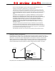
QA review draft1 ES2440 Hardware Guide: Installation 2.1.2 Grounding: Ground the ES2440 by connecting a ground wire to the grounding stud located on the left rear corner of the chassis (refer to Figure 2.1). Radio Frequency: The Mesh Point’s internal radios conform to the FCC’s safety standard for human exposure to RF electromagnetic energy, provided that you follow these guidelines: Do not touch or move the antennas while the unit is transmitting or receiving.
QA review draft1 ES2440 Hardware Guide: Installation deployment. Use the resulting connector/cord assembly to connect the ES2440 to an external 30 VDC power source. 2.1.3 Port and Grounding Stud Locations The ES2440 Mesh Point’s Serial port and three Ethernet ports, Ethernet1/WAN/POE, Ethernet2, and Ethernet3 are located on the front panel, along with the DC Power inlet and recessed Reset button (see Figure 2.1).
QA review draft1 ES2440 Hardware Guide: Installation internal radios, as shown below, and one for the ES2440 internal GPS. antenna port 1 Radio 1 antenna port 1 Radio 2 antenna port 1 Radio 3 antenna port 1 Radio 4 GPS antenna port antenna port 2 Radio 4 antenna port 2 Radio 3 antenna port 2 Radio 2 antenna port 2 Radio 1 Figure 2.2.
QA review draft1 ES2440 Hardware Guide: Installation 2.2.2 Connections for Deployment Review the Safety Requirements in (Section 2.1.1) before installing or operating the ES2440. 1 Ground the ES2440 by connecting a ground wire to the ES2440’s grounding stud located on the left rear corner of the chassis (refer to Figure 2.1). 2 If your deployment uses Radio 1, connect a standard 2.4 GHz- or 5 GHz-capable antenna with an N-type male connector, to antenna port 1 (Ant1).
QA review draft1 ES2440 Hardware Guide: Installation extending from the Mesh Point through the holes in the bracket. Figure 2.3. Mast mounting the ES2440 5 Place a slip-lock washer and then a wing nut on each of the bolt ends, and tighten the nuts until the washers are flattened against the mounting bracket.
QA review draft1 ES2440 Hardware Guide: LEDs and Button Operation Chapter 3 LEDs and Button Operation 3.1 Front-Panel LED Indicators The ES2440 Mesh Point features nine LEDs on the front panel (shown in Figure 2.1). can exhibit: solid green - Mesh Point is powered on and operating normally. off - Mesh Point is powered off. slow-flash green - Mesh Point is booting. Power Status can exhibit: intermittent green - Cleartext is passing on an encrypted port.
QA review draft1 ES2440 Hardware Guide: LEDs and Button Operation 3.2 Recessed Button Operation The single recessed button on the ES2440 front panel (shown in Figure 2.1) returns the ES2440 Mesh Point to the factory default configuration. The button is covered by a screw cap that you must remove, in order to access the button. You must replace the screw cap, in order to maintain the watertight integrity of the ES2440 chassis. To restore default settings, depress and hold the button for 10 seconds.
QA review draft1 ES2440 Hardware Guide: Specifications Chapter 4 Specifications 4.1 4.1.1 Hardware Specifications Physical Specifications form factor: mountable, compact, rugged chassis dimensions: 2.75" H x 8.5” W x 9.5” D (6.99 cm x 21.59 cm x 24.13 cm) 7 lbs (3.18 kg) weight: 802.
QA review draft1 ES2440 Hardware Guide: Specifications 4.1.3 Compliance and Standards CE, FCC, ETSI, CB Test, MIL-STD 464A, MIL-STD 461F emissions/immunity: vibration: MIL-STD 810G weather resistance: IP67 submersible The Fortress ES2440 is certified by the Wi-Fi Alliance® for the following standards: IEEE: 802.11a/b/g/n security: EAP types: 4.
QA review draft1 ES2440 Hardware Guide: Specifications Table 4.1. RJ45-to-DBP Adapter Pin-Outs 4.3 RJ45 pin DB9 pin standard color 7 4 orange 8 7 blue 2-Pin DC Input Connector As described in Section 2.1.2, Powering Options, the connector-cable assembly to power the ES2440 through its weathertight 2-pin DC input is not included with the ES2440. Mating connectors include the Amphenol® MIL-C-26482, Series 1, part #MS3116J10-2S, Miniature Cylindrical Connector. Figure 4.
QA review draft1 ES2440 Hardware Guide: Index Index Numerics G 4.4 GHz see military band radios 802.11a/b/g/n see radios 802.
QA review draft1 ES2440 Hardware Guide: Index R radios 2 connecting antennas 7, 8 LEDs 10 precautions v, 2, 8 safety requirements 5 specifications 12 RJ-45-to-DB9 adapter 13–14 S safety precautions 1, 5, 8 requirements 4–5 see also specifications serial port adapter 13–14 location 6 specifications 12–13 T TDWR i–iii V VDC input 5–6 connecting 7 location 6 pin-outs 14 specifications vibration 13 12 II