
User's Manual
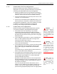
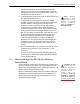
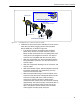
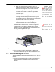
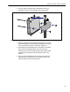
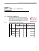
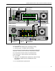
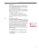
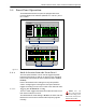
Table Of Contents

ES520 Hardware Guide: Installation
17
CAUTION: There
are four different
possible alignments be-
tween the RJ-45 connec-
tor and the connector
boot. If the boot and
connector are not in the
correct alignment, the
RJ-45 connector will not
plug into the Mesh
Point’s WAN port.
Align the primary key tab on the inner ring of the
connector boot with the cable connector’s locking tab.
Maintaining this alignment, fit the RJ-45 connector-
collar assembly into the boot through the boot’s
threaded end and snap the collar tabs into the boot
slots. Screw the connector boot securely onto the
threaded coupler.
Fit the compression bushing into the flanged end of the
threaded connector, and fit the compression nut over
the flanges. Screw the compression nut securely onto
the threaded connector until the bushing is compressed
around the cable to provide a water seal.
Step 5 of Section 2.2.2 describes plugging the
connector/boot into the Mesh Point’s WAN port.
WARNING: To
avoid the risk of
severe electrical shock,
do not remove the cover
plate while the Fortress
Mesh Point is out of
doors.
2 Attach the cover plate to the Mesh Point’s front panel with
the plate’s three captive screws, as shown in Figure 2.4.
The front-panel cover plate for ES520 version 2 Mesh
Points features an additional opening for the weatherized,
locking, multi-range DC power input.
Figure 2.4. Attaching the Front-panel Cover Plate for an ES520 version 1
3 If only one antenna will be attached to the Mesh Point,
screw the antenna port cap onto the unused antenna port.
2.4 Mast Mounting the ES520
The Mast-Mounting Kit accommodates masts from 1.5" to 3" in
diameter.
1 Fit the two hex bolts through the center mounting holes in
the lip extensions of the Mesh Point’s underside, top to
bottom.