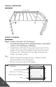
INSTALLATION INSTRUCTIONS EVOLUTION PERGOLA KIT 10' x 14'
TABLE OF CONTENTS Introduction General Guidelines...............................................................3 Required Tools/Components...............................................4 Installation Overall Dimension................................................................6 Project Planning...................................................................6 Pergola Assembly Mount Post to Pier Brackets onto Ground Surface.....................................................................
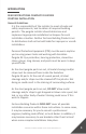
INTRODUCTION READ INSTRUCTIONS COMPLETELY BEFORE STARTING INSTALLATION General Guidelines It is the responsibility of the installer to meet all code and safety requirements, and to obtain all required building permits. The pergola installer should determine and implement appropriate installation techniques for each installation situation. Neither Fortress Building Products nor its distributors shall not be held liable for improper or unsafe installations.
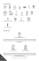
Required Tools Goggles Ear Protector Safety Gloves Tape Measure Close-Toed Shoes Hex Head Nut Driver Bits: 9/16”, 5/16” [14mm, 8mm] Speed Square Touch-Up Paint Step Ladders Pencil Level Bit Extender Ratchet Wrench: 9/16” [14mm] Speed Clamps Wrench: 9/16” [14mm] Concrete Anchor: 3/8” x 3” [10mm x 76mm] Components A: Post to Pier Bracket (x4) B: Post (x4) 3-1/2” x 3-1/2” x 96” C: F-50 (x8) Post to Framing Joists D: F-50 (x14) Framing to Rafter Joists E: Short Framing Joist (x2) 2” x 6
F: Long Framing Joist (x2) 2” x 6” x 160-11/16” [51mm x 152mm x 4082mm] G: Rafter Joist (x7) 2” x 6” x 115-3/4” [51mm x 152mm x 2939mm] H: Lateral Bracing Bracket (x16) J: Post Cap (x4) 3-1/2” x 3-1/2” [89mm x 89mm] Note: • • I: Lateral Bracing Support(x8) 2” x 2” x 24” [51mm x 152mm x 610mm] K: Evolution Self-drilling Screw (Bag of 250) 3/4” [19mm] #12 212 screws (Component K) are required to complete an installation. Additional screws are provided to account for damaged or lost screws.
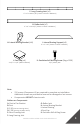
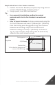
OVERALL DIMENSIONS 168” [4267mm] 12 [3 04 0m m ] 97” [24 64m m] 0” PROJECT PLANNING Step 1: Create a Perimeter For The Pergola 1. This Evolution Pergola Kit is designed to have a perimeter of 168” x 120” [4267mm x 3040mm]. 2. Using Stakes and Guide String create a perimeter for the pergola. Each side of the pergola should be positioned a minimum of 4” [102mm] from the edge of the ground surface. As shown in Fig. 1.
Step 2: Mark Post to Pier Bracket Locations 1. Position Post to Pier Brackets (component A) along internal corners of Guide Strings. As shown in Fig. 2. 2. Using a pencil, mark bolt hole locations. Tip: • For a successful installation, confirm the created perimeter with Post to Pier Brackets is accurate and square. • How To Square Perimeter: Fortress recommends using the 3-4-5 rule. Measure and mark 3’ [914mm] & 4’ [1219mm] from the starting point along guide string, then measure between two markings.
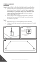
PERGOLA ASSEMBLY Step 1: Mount Post to Pier Brackets (x4) onto Ground Surface 1. Confirm the Post to Pier Brackets (component A) are in desired positioned. Adjust if needed. For a successful installation, It is critical for Post to Pier Brackets to be square and positioned correctly. Reference project planning on pages 6 and 7. 2. Mount Post to Pier Brackets (component A) onto the ground surface using 3/8” [10mm] Concrete Anchors. As shown in Fig. 3 & 4. Note: • Reference Fig.
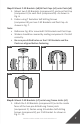
Step 2: Mount F-50 Brackets (x8) & Post Caps (x4) onto Posts (x4) 1. Mount two F-50 Brackets (component C) and one Post Cap (component J) to each Post (component B). As shown in Fig. 6. 2. Fasten using 7 Evolution Self-drilling Screws (component K) per two F-50 Brackets and Post Cap. As shown in Fig. 7. Note: • Reference Fig. 8 for mounted F-50 Brackets and Post Caps. • Stickers should be covered by mating components if install correctly.
Note: • Reference Fig. 12 for mounted F-50 Brackets. • Stickers should be covered by mating components if install correctly. • Be sure pre-drilled holes on the Long Frame Joists and the F-50 Brackets are aligned before fastening. • DO NOT mount F-50 Brackets onto the outside face of the Long Frame Joist in this step. As shown in fig. 13 Fig. 9 Fig. 10 Fig.
Fig. 12 x2 Fig. 13 Inside Face Outside Face Step 4: Mount Short Frame Joists (x2) onto Posts (x4) 1. Mount each Short Frame Joist (Component E) onto F-50 Brackets (component C) that are attached to Posts (component B). As shown in Fig. 14 & 15. 2. Be sure drainage holes and pre-drilled screw holes on the Short Frame Joists face down once installed. As shown in Fig. 16. Adjust if required. 3. Fasten using 3 Evolution Self-drilling Screws (component K) per F-50 Bracket. As shown in Fig. 17.
Fig. 14 Fig. 15 Fig. 16 Drainage holes & pre-drilled screw holes facing down Fig.
Fig. 18 Front View Installed Short Frame Joist (Component E) x2 Step 5: Mount Posts (x4) into Each Post to Pier Bracket (x4) 1. Insert the two Short Frame Joist & Post assemblies (Step 4) into the mounted Post the Pier Brackets (component A). As shown in Fig. 19 & 20. 2. Fasten using 8 Evolution Self-drilling Screws (component K) per Post to Pier Bracket. As shown in Fig. 21. Note: • Reference Fig. 22 for mounted Post to Pier Brackets and Short Frame Joists.
Fig. 20 Fig. 22 Installed Short Frame Joist (Component E) Installed Post to Pier Brackets (Component A) Fig. 21 Installed Short Frame Joist (Component E) Installed Post to Pier Brackets (Component A) Step 6: Mount Long Frame Joists (x2) onto Posts (x4) 1. Mount each Long Frame Joist (Component F) onto F-50 Brackets (component C) that are attached to Posts (component B). As shown in Fig. 23 & 24. 2. Be sure drainage holes and pre-drilled screw holes on the Long Frame Joists face down once installed.
Fig. 23 Fig. 24 Fig. 25 Drainage holes & pre-drilled screw holes facing down Fig.
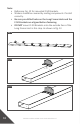
Fig. 27 Installed Long Frame Joist (Component F) Installed Long Frame Joist (Component F) Step 7: Mount Rafter Joists (x7) Between Two Long Frame Joists 1. Mount each Rafter Joist (Component G) onto F-50 Brackets (component D) that are attached to Long Frame Joists (Component F). F-50 Brackets will be mounted on opposite faces of the Rafter Joist. As shown in Fig. 28 - 30. 2. Be sure drainage holes and pre-drilled screw holes on the Rafter Joists face down once installed. As shown in Fig. 31.
Fig. 29 Fig. 30 F-50 Brackets mounted on opposite faces of Rafter Joists (Component G) Fig. 31 Drainage holes facing down Fig. 32 Fig.
Fig. 34 Installed Rafter Joists (Component G) Installed Rafter Joists (Component G) Step 8: Mount Lateral Bracing Brackets (x16) into Lateral Bracing Supports (x8) 1. Insert two Lateral Bracing Brackets (component H) into both ends of each Lateral Bracing Support (Component I). As shown in Fig. 35. Note: • DO NOT fasten Lateral Bracing Brackets onto the Lateral Bracing Support in this step. • Reference Fig. 36 for assembled Lateral Bracing.
Step 9: Mount Lateral Bracing Assemblies (x8) onto Posts and Frame Joists 1. Mount two Lateral Bracing Assemblies onto each post (component B) and bottom face of a Frame Joist (component E or F). As shown in Fig. 37 & 38. 2. Once the pergola is square, fasten Lateral Bracing Assemblies through pre-drilled holes on Post or Frame Joist using 4 Evolution Self-Drilling Screws (component K) per Lateral Bracing Assemby. As shown in Fig. 39. 3.
Fig. 39 Fig. 40 Fig. 41 Installed Lateral Bracing Assembly Installed Lateral Bracing Assembly Step 10: Apply Spray Paint to Scratched Areas 1. Identify the areas of the pergola that have been scratched during installation and apply two coats of Fortress Black Sand Touch Up Paint. Fig.
CARE & MAINTENANCE Care And Maintenance Of Fortress Building Products Powder-Coated Products And Surfaces: • • • • • Immediately after installation of your Fortress Building Products, clean powder-coated products and surfaces with a solution of warm water and non-abrasive, pH neutral detergent solution. Surfaces should be thoroughly rinsed after cleaning to remove all residues. All surfaces should be cleaned using a soft cloth or sponge.
JOIN THE REVOLUTION. FortressBP.com | 866.323.4766 © 2022 Fortress Building Products. Unless otherwise noted, all proprietary names are trademarks of Fortress Iron, LP. All rights reserved.