INSTALLATION INSTRUCTIONS INSPIRE ALUMINUM RAILING INSPIRE RAILING INSTALLATION 1
TABLE OF CONTENTS English 2 Introduction.........................................................................3 Level Bracket........................................................................4 Angle Bracket.....................................................................16 Stair Bracket.......................................................................20 Care & Maintenance/ Warranty.........................................
INTRODUCTION READ INSTRUCTIONS COMPLETELY BEFORE STARTING INSTALLATION It is the responsibility of the installer to meet all code and safety requirements, and to obtain all required building permits. The deck and railing installer should determine and implement appropriate installation techniques for each installation situation. Fortress Building Products and its distributors shall not be held liable for improper or unsafe installations.
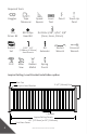
Required Tools Goggles T-25 Driver Bit Socket Set Drill Tape Measurer Speed Square #2 Phillips Head Bit 3/32”, 1/4” [2.38mm, 6.
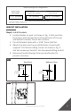
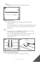
Inspire Railing Post Configuration Inspire Railing Panel Height Inspire Railing Panel Installed Panel Height* 32-1/2” [826mm] Required Post 39-1/2” [1003mm] 36” [914mm] *Installed heights include a 3-1/2” [89mm] space between deck surface and bottom edge of bottom rail. BRACKET INSTALLATION Step 1: Install Brackets 1. Locate dimples on post. As shown in Fig. 1. Each post has three faces with dimples for the bracket holes of the top and bottom brackets, fourth face is blank. 2.
POST MOUNTING *If using Fortress Evolution Framing, contact Fortress for instructions. Step 1: Install Wood Blocks 1. Install Wood Block level with top of joist. As shown in Fig. 1. 2. Secure Wood Block to blocking on all four sides with #10 X 3-1/2” [89mm] deck screws. • Wood Block must be constructed with treated dimensional lumber with a minimum thickness of 1-1/2” [38mm]. Fig. 1 Wood Block Joist Blocking Wood Block #10 x 3-1/3” [85mm] Step 2: Position Base Plate 1.
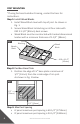
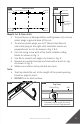
Note: • DO NOT exceed the maximum post spacing. Fig. 1 6’ panel maximum post spacing is 69-1/4” [1759mm] 8’ panel maximum post spacing is 93-1/4” [2369mm] Check measurement with top Step 5: Check Mounted Posts 1. Shim post as needed to ensure post is level. 7 OTP and Proud Post: Max Post Spacing • 8’ panel maximum post spacing is 93-7/8”. • 6’ panel maximum post spacing is 69-7/8”. Note: Do not exceed the maximum post spacing.
Fig. 1 Fig. 2 Shim post as needed to ensure post is level Wood Block 1/2” [13mm] Deck Board Rim Joist Joist / Blocking CUTTING DOWN BOTTOM AND TOP RAILS Step 1: Measure The Panel Opening Length 1. Measure panel opening distance. As shown in Fig. 1. 2. Confirm that the measurements for the top brackets are the same as the bottom brackets. Tip: • Measure from the back wall of the bracket to the back wall of the bracket on other post. As shown in Fig. 2. Fig. 1 Fig.
Fig. 1 Mark Here Center of Rails Half of Panel Length Fig. 2 Mark Here Cut mark Maximum 4” [102mm] spacing Mark Here Mark Here Step 3: Cut & Clean Rails 1. To avoid injury or damage before cutting down rail, remove picket plugs in general area of the cut. 2. To remove picket plugs, use 1/4” [6mm] Hex Wrench and rotate plug to the right until indication marks are perpendicular to rail. As shown in Fig. 1 & 2. 3. Cut rails using a saw with a fine tooth carbide cutting blade. As shown in Fig. 3. 4.
Fig. 3 Fig. 4 Fig. 5 Step 4: Apply Spray Paint To Cut Areas 1. Using a piece of cardboard as a mask, apply the 1st coat of Fortress zinc based touch-up paint. 2. Allow to dry before applying second coat. 3. Apply the 2nd coat of Fortress zinc based touch-up paint. 4. Allow to dry and install. Fig. 1 2X PANEL INSTALLATION Step 1: Inspect Top and Bottom Rails 1. Confirm that the indication marks on the top of the picket plugs are parallel to the rail. As shown in Fig. 1. 2.
Fig. 1 Fig. 2 Top View Rail Fig. 3 Picket Plug Top View Top Rail Bottom Rail Plug with “B” stamp for bottom rail Step 2: Assemble Panel 1. Level panels have 3 Support Pickets with threaded ends. As shown in Fig. 1. 2. Lay all panel components on a flat surface. Support Pickets are labeled with removable stickers. 3. Place a Support Picket at both ends of the panel and one in the center of panel. 4. Fasten Support Pickets to the bottom rail using included T-25 M6 Flat Head Bolt. As shown in Fig.
Fig. 1 Support Picket (Section View) T-25 M6 Flat Head Bolt Thread 1 Fig. 2 2 3 Fig. 3 Fig. 4 Step 3: Install Top Rail Cap onto Top Rail 1. Slide the top rail cap on to the top rail. As shown in Fig. 1. Fig.
Step 4: Install I-support onto Bottom Rail 1. Position the I-support as close to the center of the bottom rail as possible. The I-support should be inserted between two pickets. As shown in Fig. 1. Use a Crescent Wrench to twist the I-Support into place As shown in Fig. 2. Fig. 1 Fig. 2 Step 5: Install Panel Into Brackets 1. Install panel into brackets to confirm proper fit. Confirm that pickets are parallel to posts. As shown in Fig. 1. 2.
Step 6: Attach I-Support To Deck 1. Pre-drill I-support screw hole with a 1/16” [2mm] drill bit. 2. Fasten I-Support to deck surface with the supplied Phillips Head Wood Screw. As shown in Fig. 1. Fig. 1 POST BASE COVER & BRACKET CAP INSTALLATION Step 1: Install Post Base Cover 1. Separate the two-piece base plate cover. Hold one side parallel to the post base plate. As shown in Fig. 1. 2. Place 2nd half of the post base cover on the opposite side of the post. Hold 2nd piece slightly under the 1st piece.
Fig. 1 Fig. 3 Fig. 2 Fig. 4 Fig. 5 Step 2: Install Bracket Caps 1. Bracket Caps snap over Bracket Cups. As shown in Fig. 1 & 2. Fig. 1 Fig.
ANGLE BRACKET Inspire Railing: Angle Bracket Installation option Post Cap 2-1/2” [64mm] Post Inspire Angle Bracket I-Support Inspire Railing Panels 69” [1753mm] or 93” [2362mm] Post Base Cover Inspire Railing Post Configuration Inspire Railing Panel Height 32-1/2” [826mm] Inspire Railing Panel Installed Panel Height* 36” [914mm] Required Post 39-1/2” [1003mm] *Installed heights include a 3-1/2” [89mm] space between deck surface and bottom edge of bottom rail.
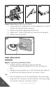
5. Remove all metal shavings from deck, post base cover, post, and panel before bracket is screwed to post. Tip: • Use a Bit Extender. Fig. 1 Fig. 2 Assembled Angle Bracket Without Cap Angle Bracket Cap (To be installed in a later step) ANGLE BRACKET: POST MOUNTING • Reference Post Mounting instructions on page 6. ANGLE BRACKET: CUTTING DOWN PANELS Step 1: Determine Panel Length 1. Use 3/32” [2mm] Hex Wrench to tighten Set Screw & lock Bracket at required angle position. As shown in Fig. 1. 2.
4. With another person’s help, measure the distance from the inside back of one cup to the inside back of the other cup. This will be the panel length. As shown in Fig. 2 & 3. Fig. 1 Bottom of Bracket Fig. 2 Fig. 3 DO NOT measure from post Measure from back of bracket Step 2: Panel Cutting Steps • Reference pages 8 - 10 for panel cutting steps.
ANGLE BRACKET: PANEL INSTALLATION • Reference pages 10 - 14 for Panel Installation steps. ANGLE BRACKET: POST BASE COVER & BRACKET CAP • Reference Post Base Cover & Bracket Cap installation instructions on pages 14 & 15.
STAIR BRACKET Inspire Railing: Stair Bracket Installation option Inspire Stair Bracket Cap Inspire Stair Bracket 2-1/2” x 51” [64mm x 1295mm] Post Post Cap Post Base Cover I-Support Stair Angle 31° to 38° Inspire Railing Post Configuration Inspire Railing Panel Height 32-1/2” [826mm] 20 Inspire Railing Panel Installed Panel Height* Required Post 36” [914mm] INSPIRE RAILING INSTALLATION 51” [1003mm]
TOP POST MOUNTING • • Reference Post Mounting instructions on page 6. Only mount the top post in this step, DO NOT mount the bottom post. As shown in Fig. 1. Fig. 1 Mount Post DO NOT Mount Post TOP POST BRACKETS INSTALLATION Step 1: Confirm Needed Bracket 1. Each Inspire Stair panel comes with two top post brackets and two bottom post brackets. Be sure to reference the sticker on the inside face of the bracket cups to confirm the bracket set being used. As shown in Fig. 1. Fig.
Step 2: Bottom Bracket Installation 1. Position wood 2” x 4” (actual 1-1/2” [38mm] x 3-1/2” [89mm]) between posts. As shown in Fig. 1. 2. Position bottom rail brackets centered flat on post & wood 2” x 4” (actual 1-1/2” [38mm] x 3-1/2” [89mm]). As shown in Fig. 2. 3. Use pencil to mark top edge of bracket location on post. As shown in Fig. 3. 4. Dis-assemble the brackets by removing the barrel and screw. 5. Place bracket base on previous top edge mark.
Step 3: Bottom Bracket Installation Continued 1. Use Spring Punch to mark the holes. As shown in Fig. 1. 2. Drill out bracket holes with a 3/16” [5mm] drill bit. As shown in Fig. 2. 3. Use T-25 Thread-Cutting Screws to attach the bracket base. Begin with top hole then bottom. As shown in Fig. 3. 4. Keep bracket base centered as you install second screw. As shown in Fig. 4. 5. Insert & tighten barrel & screw to re-assemble bracket. As shown in Fig. 5. Fig. 1 Fig. 2 Fig. 3 Fig. 4 Fig.
Step 4: Top Bracket Installation 1. Position wood 2” x 4” (actual 1-1/2” [38mm] x 3-1/2” [89mm]) under bottom bracket. As shown in Fig. 1. 2. Fully rake and place panel next to posts on top of wood 2” x 4” (actual 1-1/2” [38mm] x 3-1/2” [89mm]). 3. Clamp panel to post in 4 places. 4. Use a level to ensure panel and posts are both straight. 5. Position top rail brackets parallel with panel & flat centered on post. Make sure inside bottom of bracket is flush with bottom of rail. As shown in Fig. 3. 6.
Step 5: Top Bracket Installation Continued 1. Use Spring Punch to mark the holes. As shown in Fig. 1. 2. Drill out holes with a 3/16” [5mm] drill bit. As shown in Fig. 2. 3. Use T-25 Thread-Cutting Screws to reattach the base of the top rail bracket to the post. 4. Insert barrel & screw to re-assemble bracket. 5. Tighten barrel & screw. As shown in Fig. 3. Fig. 1 Fig. 2 Fig. 3 BOTTOM POST MOUNTING Step 1: Mark Bottom Post Mounting Location 1.
3. Position bracket centered flat on bottom post & wood 2” x 4” (actual 1-1/2” [38mm] x 3-1/2” [89mm]). As shown in Fig. 2. 4. Check end picket positioning on both bottom brackets. Pickets SHOULD NOT be positioned inside the bracket cup spacing. As shown in Fig. 3 & 4. 5. Adjust the unmounted bottom post’s position to allow for correction to end picket position. As shown in Fig. 5. The post to picket spacing CANNOT exceed 4” [102mm]. 6.
Fig. 6 Fig. 5 Fig. 7 Position inside bottom face of Bracket flush with bottom of rail Fig. 8 Step 2: Mount Bottom Post • Reference Post Mounting instructions on page 6. BOTTOM POST BRACKETS INSTALLATION • Reference top post bracket installation instructions on pages 21 - 25. CUTTING DOWN PANEL Step 1: Measure & Mark Panels Where Cuts Will Be Made 1. Position wood 2” x 4” (actual 1-1/2” [38mm] x 3-1/2” [89mm]) under bottom brackets. 2.
3. Check end picket positioning on all brackets, pickets SHOULD NOT be positioned inside the bracket cup spacing. As shown in Fig. 1 & 2. 4. Measure spacing from inside edge of post to the picket. Spacing CANNOT exceed 4” [102mm] on each end. As shown in Fig. 3. 5. Use a level to ensure pickets and posts are both straight. 6. If needed, use shims to level the posts. 7. Clamp panel to post in 4 places. 8. Mark cut points on panels in line with the back of bracket opening.
PANEL INSTALLATION Step 1: Mount I-Support To Bottom Rail 1. Locate the center of the bottom rail. The I-support should be centered and positioned between two pickets. As shown in Fig. 1. 2. Using the I-Support as a guide, mark the center of the 2 screw holes. As shown in Fig. 2. 3. Using a 3/16” [5mm] drill bit, drill though the outside wall. 4. Install the I-Support with the provided Phillips Head Thread Cutting Screws. As shown in Fig. 3. Fig. 1 Fig. 2 Fig. 3 Step 2: Install Panel 1.
Fig. 1 Step 3: Attach Panel To Brackets 1. Pre-drill holes for screws using a 3/16” [5mm] drill bit. 2. Push the bracket up so that the bottom face is parallel with the bottom face of rail. As shown in Fig. 1. 3. Attach the panel to brackets using the T-25 thread-cutting screws that came with the brackets. Two screws are required in each bracket. As shown in Fig. 2. 4. Remove any metal shavings after attaching the panel. Fig. 1 Fig. 2 Step 4: Mount I-Support To Deck Surface 1.
Fig. 1 Fig. 2 STAIR BRACKET: POST BASE COVER & BRACKET CAP INSTALLATION • Reference Post Base Cover & Bracket Cap installation instructions on pages 14 & 15.
CARE & MAINTENANCE Care And Maintenance Of Fortress Building Products Powder-Coated Products And Surfaces: • • • • Immediately after installation of your Fortress Building Products, clean powder-coated products and surfaces with a solution of warm water and non-abrasive, pH neutral detergent solution. Surfaces should be thoroughly rinsed after cleaning to remove all residues. All surfaces should be cleaned using a soft cloth or sponge.
INSPIRE RAILING INSTALLATION 33
JOIN THE REVOLUTION. FortressBP.com | 866.323.4766 © 2021 Fortress Building Products. Unless otherwise noted, all proprietary names are trademarks of Fortress Iron, LP. All rights reserved.