INSTALLATION INSTRUCTIONS Al13+ PVC DECKING ALUMINUM RAILING APEX DECKING & Al13 PLUS ALUMINUM RAILING DECK & STAIR KIT INSTALLATION: APEX DECKING & Al13 PLUS RAILING 1
TABLE OF CONTENTS Introduction General Guidelines...............................................................3 Pre-Construction Checklist/ Design Checklist......................4 Tables...................................................................................5 Required Tools/Components: Apex Decking........................6 Components: : Al13 PLUS Traditional Railing........................7 Installation Installation Overview............................................................
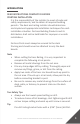
INTRODUCTION READ INSTRUCTIONS COMPLETELY BEFORE STARTING INSTALLATION It is the responsibility of the installer to meet all code and safety requirements, and to obtain all required building permits. The deck and railing installer should determine and implement appropriate installation techniques for each installation situation. Fortress Building Products and its distributors shall not be held liable for improper or unsafe installations.
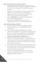
Apex Deck Board Pre-Construction Checklist • Store Apex boards on a flat surface, supported every 2’ [610mm]. Improper storage from supports >2’ [610mm] O.C. can result in a waviness that will be visible when installed. • Apex boards are pre-finished. As with any pre-finished product, care must be taken prior to installation. • Keep Apex boards covered and protected from dirt, debris, mortar and cementicious material. • Fortress WILL NOT be responsible for installation of blemished or damage product.
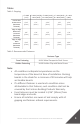
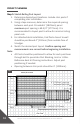
Tables Table 1: Gapping If < 30oF If > 30oF (-1oC) & If > 50oF (11oC) If > 70oF (22oC) (-1oC) < 50oF (10oC) & < 70oF (21oC) & < 90oF (32oC) End-To-End & Butt Joints (Minimum Allowed) Edge-To-Edge When Face Fastened (Minimum Allowed) Edge-To-Edge With HULK HFS (Minimum Allowed) If > 90oF (32oC) 5/16” [8mm] 1/4” [6mm] 3/16” [5mm] 1/8” [3mm] 1/16” [2mm] 1/8” [3mm] 1/8” [3mm] 1/8” [3mm] 1/8” [3mm] 1/8” [3mm] 3/16” [5mm] 3/16” [5mm] 3/16” [5mm] 3/16” [5mm] 3/16” [5mm] Table 2: Recommended Fasten
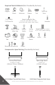
Required Tools & Material (Not Provided By Fortress) Goggles Safety Gloves T-25, T-20 & T-15 Driver Bit Drill Metal Cutting Miter Saw Table Saw Circular Saw Wrenches & Socket Set Tape Measurer Speed Square Level Tool Touch-Up Paint Metal Cutting Drill Bits: 1/16”, 1/8", 3/16”, 3/8”, 7/16", 9/16" [2mm, 3mm, 5mm, 10mm, 11mm, 14mm] Rubber Mallet Dust Mask Spring Punch Hard-Bristled Broom Bit Extender Wood Block 2” x 4” (actual 1-1/2” x 3-1/2” [38mm x 89mm]) Pencil File Clamps Components:
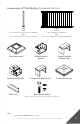
Components: Al13 PLUS Railing (Provided By Fortress) Post Level: 3" x 3" 39-1/2" [76mm x 76mm x 1003mm] Stair: 3" x 3" 45-1/2" [76mm x 76mm x 1156mm] Post Base Cover Evolve Stair Bracket U-Rim Joist Note: • Panel Level: 34" x 6’ [864mm x 1829mm] Stair: 34" x 6' or 8’ [864mm x 1829mm or 2438mm] Evolve External Bracket Evolve External Bracket Cap Evolve Stair Bracket Cap Pressed Dome Cap Bolt, Washer & Nut 3/8” x 4" and or 8-1/2" [10mm x 102mm or 216mm] Components ARE NOT shown to scale.
INSTALLATION OVERVIEW Apex Decking & Al13 PLUS Railing Without Stair Kit Apex Decking & Al13 PLUS Railing With Stair Kit 8 DECK & STAIR KIT INSTALLATION: APEX DECKING & Al13 PLUS RAILING
Apex Decking & Al13 PLUS Railing Installation Process (Overview) 1. Mount Picture Frame Deck Boards 2. Mount Infill Deck Boards 3. Mount Stair Deck Boards (Optional) 4. Install Railing Post & Brackets 5. Install Railing Panels 6. Mount Stair Posts & Panels (Optional) Note: Construction methodologies are always improving. Please visit FortressBP.com for the most up-to-date Installation Instructions.
PROJECT PLANNING Step 1: Sketch Railing Post Layout 1. Determine desired post locations. Include stair posts if completing stair installation. 2. Using a tape measure, determine the required spacing between each post. Provided 6’ [1829mm] panel maximum post spacing is 69-3/4” [1772mm]. It is recommended to layout post to allow for minimal railing panel cuts. 3. For attached deck installation, End Posts closest to wall should be positioned 4" [102mm] from outside face of S-Ledger. 4.
DECK & STAIR KIT INSTALLATION: APEX DECKING & Al13 PLUS RAILING 11
INSTALLATION: PICTURE FRAME DECK BOARDS Free-standing Installation Attached Installation Step 1: Cut Square Edge Deck Boards Deck Boards to Length 1. For Free-standing Deck installation: Cut four square edge deck boards to desired length. Measure edge to edge distance of each end of frame. Be sure cut lengths account for 1/2" [13mm] overhang on both ends when mounted. As shown in Fig. 2 & 3. Reference Table 1: gapping on page 5 to account for weather condition impact on boards. 2.
Fig. 2 Measure edge to edge length Measure edge to edge length Top View Fig. 3 Square Edge Deck Board Free-standing Deck installation: Desired length (x4) Attached Deck installation: Desired length (x3) Reference gapping table on page 5 Top View Step 2: Miter Cut Square Edge Deck Boards 1. For Free-standing Deck installation: Cut both ends of all four boards at 45⁰ angles. As shown in Fig. 4. 2.
Fig. 5 Attached Deck installation Square Edge Deck Board 45 45o o (x1) Square Edge Deck Board 45 o (x2) Top View Step 3: Mount Cut Square Edge Deck Boards as Picture Frame 1. For Free-standing Deck installation: Position cut Square Edge Deck Boards onto top face of four ends of deck frame. As shown in Fig. 6. 2. For Attached Deck installation: Position cut Square Edge Deck Boards onto top face of front and each side of the deck framing. As shown in Fig. 6. 3.
HOUSE/BUILDING Fig. 6 HOUSE/BUILDING Top View Free-standing Deck installation Fig. 7 Square Edge Deck Board Attached Deck installation Fig. 8 1/2” [13mm] Deck Board Overhang 1/2” [13mm] Deck Board Overhang Evolution Framing Beam Front View Square Edge Deck Board Side View Evolution Framing End Joist Fig. 9 Gapping is temperature dependent. Reference End-To-End row table 1 on page 5. Top View Fig.
Fig. 11 Evolution Framing Joist Gapping is temperature dependent. Reference table 1 on page 5.
INSTALLATION: INFILL DECK BOARDS Free-standing Deck Installation Attached Deck Installation Step 1: Cut Infill Grooved Deck Boards 1. Measure opening between internal faces of the two side Picture Frame deck boards. As shown in Fig. 12. Be sure to account for required gapping between ends of Infill Boards and side of Picture Frame boards. Gapping is temperature dependent. Reference End-To-End and Butt Joints row of table 1 on page 5. 2. Cut Grooved Deck Boards to determined Length. As shown in Fig. 13.
Fig. 13 Grooved Deck Board Determined Length Top View Step 2: Mount First Infill Grooved Deck Board 1. Position first Infill Grooved Deck Board so that it has equal gapping at both ends and a 3/16" [5mm] gap between front Picture Frame Board and Infill Grooved Deck Board. As shown in Fig. 14. 2. Face fasten first Infill Grooved Deck Board along its length on edge closest to front Picture Frame Board using HULK Metal Composite Deck screws. As shown in Fig. 14. Fig.
• HULK hidden Clip screw should be driven into cavity of the clip until tensioned against clip body. DO NOT over drive screw past this point. As Shown In Fig. 18. 3. Insert the second cut Infill Grooved Board at an angle allowing it to engage with the exposed end of the HULK Hidden Clips with Metal Screws. As shown in Fig. 19. 4. While pressing down, push the second Board towards the first board with HULK Hidden Clips engaged with both boards. As shown in Fig. 20.
Fig. 18 Fig. 19 Infill Board 2 Fig. 20 Infill Board 1 Push Infill Board 2 Infill Board 1 Step 4: Mount Final Infill Deck Board Free-Standing Deck installation: 1. Measure remaining opening. As shown in Fig. 21. 2. Minus 3/8" [10mm] from measured opening to account for required 3/16" [5mm] gapping on each side of board once mounted. 3. Rip final Grooved Deck Board (cut along its length) to determined width. 4.
3. Rip final Square Edge Deck Board (cut along its length) to determined width. 4. Reference step 3: 6 on page 14 for face fastening final Infill Square Edge Board. Note: • Be sure gapping at ends of final board is consistent with gapping at ends of previous boards. • Use a Table Saw to rip cut final board. • It is recommended to wear a dust mask when cutting. Measure remaining opening between edges of deck boards Fig. 21 Free-standing Deck installation Top View Fig.
INSTALLATION: STAIR DECK BOARDS Square Edge Deck Boards Step 1: Mount Stair Deck Boards 1. Cut the required amount of Square Edge Deck Board to 47-7/8” [1216mm] lengths. As shown in Fig. 23. Each Stair Tray requires two deck boards. 2. Position first cut Square Edge Deck Board against the back lip of the Stair Tray and center across the width of the Stair Tray. As shown in Fig. 24. 3.
6. Use HULK Metal Composite Deck Screws to fasten each end of the deck board onto top face of stair frame. Reference Fig. 28 & 29 for recommended fastener spacing. 7. Position second cut Square Edge Deck Board flush with the side face of the stair tray and spaced 1/8" [3mm] from the first board. As shown in Fig. 30. 8. Repeat Step 1: 3 - 6. As shown in Fig. 31 - 35. 9. Repeat Step 1: 1 - 8 to install Square Edge Deck Boards onto remaining steps in stair frame. As shown in Fig. 36.
Fig. 25 Fig. 26 Wood Block Fig. 27 Square Edge Deck Board Drilled holes: 1/8" [3mm] deep Bottom View Fig. 28 Fig. 29 1-3/16” [30mm] fastener spacing from each edge Top View Fig.
Fig. 31 Fig. 32 Wood Block 1/8” [3mm] gapping between board edges Fig. 33 Square Edge Deck Board Drilled holes: 1/8" [3mm] deep Bottom View Fig. 34 Fig. 35 1/8” [325mm] gapping between board edges 1-3/16” [30mm] fastener spacing from each edge Top View Fig.
INSTALLATION: EVOLVE EXTERNAL BRACKET Al13 3" [76mm] Post Evolve External Bracket Step 1: Identify Required Post & Bracket Configurations 1. Based on your post layout, determine required bracket configurations for each post. Reference Fig. 37 below. Note: • Reference project planning steps on pages 10 & 11 for post layout. Fig. 37 Post Configurations TOP VIEW END POST LINE POST CORNER POST Step 2: Mark Bracket Hole Locations onto Posts 1. Mark the centerline of each post with a pencil. 2.
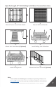
Fig. 38 Evolve External Bracket Hole Locations: Pre-drill Dimensions: Pre-drilling with a 3/16” [5mm] drill bit is required 34” [864mm] Panel A* B C D 3-13/16” [97mm] 1/2” [13mm] 36-11/16” [932mm] 13/16” [21mm] *Dimension A positions bottom edge of rail 3-1/2” [89mm] above deck surface. *Dimension A is measured from the bottom surface of post base. Fig.
Fig. 40 Fig. 41 Fig. 42 Fig.
INSTALLATION: Al13 PLUS RAILING POSTS Al13 PLUS 3" [76mm] Post with mounted UB-04 brackets Step 1: Place Posts into Desired Position on Decking 1. Position End, Line and Corner Posts in desired position on deck surface. As shown in Fig. 44 or 45. For stair installation, ONLY position posts to be used at top of stair, bottom stair posts will be mounted in later steps. 2. Position the edge of each post base plate 1" [25mm] from Picture Frame Deck Board edges. As shown in Fig. 46. 3. Confirm post spacing.
• Additional reference point if deck boards are not straight: the edge of post base should be positioned 1/2" [13mm] from a perimeter framing Joist. Fig. 44 End Post HOUSE/BUILDING Line Post Corner Post Fig.
Fig. 46 Fig. 47 1" [25mm] Offset Top View 6’ [1829mm] panel maximum post spacing is 69-3/4” [1772mm] 1" [25mm] Offset Fig. 48 Side View Wall Surface Railing Post 3-7/8" [98mm] Post to S-Ledger Offset S-Ledger Side View Step 2: Mark & Pre-Drill Bolt Holes 1. Mark bolt hole locations and drill a 7/16” [11mm] hole. As shown in Fig. 49 & 50. Tip: • A 4" [102mm] drill bit is recommended for initial hole through framing member and 12" [305mm] is recommended for creating final hole.
Step 3: Mount Posts 1. Insert 3/8” x 8-1/2” [10mm x 216mm] Hex Head bolts and washers through pre-drilled holes. As shown in Fig. 51. 2. Fasten nuts and washers onto bolts on bottom of framing. As shown in Fig. 52. Fig. 51 Fig. 52 Step 4: Check Mounted Posts 1. Shim post as needed to ensure post is level. Fig. 53 Shim post as needed to ensure post is level Fig.
INSTALLATION: Al13 PLUS RAILING PANELS Al13 PLUS Panel Step 1: Measure The Panel Opening Length 1. Measure the distance of the panel opening. As shown in Fig. 55. Confirm that the measurements for the top brackets are the same as the bottom brackets. Tip: • Measure from the back wall of the bracket to the back wall of the bracket on other post. As shown in Fig. 56. Fig. 55 Fig.
Step 2: Measure & Mark Panel Where Cuts Will Be Made 1. To ensure rails are symmetrical, take the measurement found in step 1 (Measure The Panel Opening Length), and divide it in half to determine the center point. 2. Find the center of the rails and measure out half of the length each direction. As shown in Fig. 57. 3. Mark these locations with a pencil on the top & bottom rail. Fig. 57 Mark Here Center of Panel Mark Here Half of Panel Length Mark Here Mark Here Step 3: Cut & Clean Panel 1.
Fig. 61 2X Step 5: Install Panel 1. Install cut panel to ensure proper fit. Fig. 62 Step 6: Attach Panel To Bottom & Top Brackets 1. Pre-drill holes for screws using a 3/16” [5mm] drill bit. 2. Apply screws into bottom & top brackets. As shown in Fig. 63. Note: • Only one screw per bracket is needed to secure the bracket to the panel. • Screws should be installed on the same side of brackets. Fig.
INSTALLATION: EVOLVE STAIR RAILING BRACKET Evolve Stair Bracket Bottom Stair Post IS NOT mounted in this step Evolve Stair Bracket Chicago Bolt Male Stair Bracket Base Chicago Bolt Female • • • • 36 Stair Bracket Cap Stair Bracket Cup Available Lengths: 6' or 8’ [1829mm or 2438mm]. Available Heights: 34”[864mm]. Adjustable Angle Range: 40° maximum. For installations with more than 7 stairs, mid-span posts will be required. Be sure to repeat stair bracket and bottom stair post installation as needed.
FOR A SUCCESSFUL INSTALLATION, IT IS REQUIRED TO MOUNT STAIR BRACKETS BEFORE MOUNTING BOTTOM STAIR POSTS Step 1: Bottom Bracket of Top Post Installation 1. Position the edge of the bottom post base plate 1/2" [13mm] from edge of the stair frame. As shown in Fig. 64. 2. Position wood 2” x 4” (actual 1-1/2” x 3-1/2” [38mm x 89mm])between posts. As shown in Fig. 65. 3. Position bottom bracket centered flat on post & wood 2” x 4” (actual 1-1/2” x 3-1/2” [38mm x 89mm]).
Step 2: Bottom Bracket of Top Post Installation Continued 1. Use Spring Punch to mark the holes. As shown in Fig. 68. 2. Drill out bracket hole with a 3/16” [5mm] drill bit. As shown in Fig. 69. 3. Use T-25 screws to attach the bracket base to the post. As shown in Fig. 70. 4. Keep bracket base centered as you install second screw. 5. Insert then tighten barrel & screw to re-assemble bracket. As shown in Fig. 71.
Step 3: Top Bracket of Top Post Installation 1. Position wood 2” x 4” (actual 1-1/2” x 3-1/2” [38mm x 89mm]) on stairs in line with bottom brackets. As shown in Fig. 72. 2. Place panel on top of wood 2” x 4” [60mm x 102mm] next to bottom brackets. As shown in Fig. 73. 3. Rake the panel until balusters are parallel to the posts. 4. Clamp the panel to the post. Be sure to clamp at four touch points to keep panel in position. As shown in Fig. 74. 5. Position top bracket centered and flat on post.
Fig. 74 Clamp Fig. 75 Clamp Mark top and side location of Stair Bracket on post Clamp Clamp Position bottom of Bracket flush with bottom of rail Fig. 76 Step 4: Top Bracket of Top Post Installation Continued • Reference bottom bracket of top post installation step 2 on page 38.
INSTALLATION: Al13 PLUS BOTTOM STAIR RAILING POSTS 3” X 3” [76mm x 76mm] with Base Cover Step 1: Position Bottom Stair Posts 1. Position the edge of the bottom post base plate 1/2" [13mm] from edge of the stair frame. As shown in Fig. 77. 2. Position wood 2” x 4” (actual 1-1/2” x 3-1/2” [38mm x 89mm]) on stairs in line with bottom brackets. 3. Place panel on top of wood 2” x 4” (actual 1-1/2” x 3-1/2” [38mm x 89mm]) next to top and bottom brackets. 4.
6. Place bottom post in desired position. Measure spacing from inside edge of post to the first picket in panel. Spacing CANNOT exceed 4” [102mm] on both top and bottom posts. As shown in Fig. 79. Adjust bottom post positioning as needed. Fig. 78 Fig. 77 Clamp Clamp 1/2" [13mm] Offset Top View Clamp Clamp Fig. 79 Post To Baluster Space Must Be Less Than 4” [102mm] Step 2: Install Bottom Stair Posts 1. Mark bolt hole locations and drill a 7/16” [11mm] hole through board and step assembly.
7. Insert 3/8” x 4” [10mm x 102mm] Hex Head bolts and washers through pre-drilled holes. As shown in Fig. 87. 8. Fasten bolts onto bottom of Stair Step using nuts and washers. As shown in Fig. 88. 9. Re-Mount Stair Step onto Stair Kit. As shown in Fig. 89. Tip: • Be sure drill is plumb when drilling. • Measured length of cut U-Rim Joist IS NOT critical. Joist can be cut 1/4" [6mm] - 3/8" [10mm] short for an easier fit into opening between Stair Brackets.
Fig. 83 Back View Measure opening Fig. 84 Fig. 85 Fig. 86 44 Fig.
Fig. 88 Fig.
INSTALLATION: Al13 PLUS STAIR RAILING PANEL Adjustable Stair Panel Stair Angle Maximum 40o Step 1: Measure & Mark Panels Where Cuts Will Be Made 1. Position wood 2” x 4” (actual 1-1/2” x 3-1/2” [38mm x 89mm]) on stairs in line with bottom and top brackets. 2. Place the panel on top of wood 2” x 4” (actual 1-1/2” x 3-1/2” [38mm x 89mm]) next to bottom brackets. 3. Have the panel raked and as close to final installation position as possible. 4. Confirm that panel is level.
Fig. 90 Mark on rail in line with the back of bracket Position inside bottom of cup flush with bottom face of rail Step 2: Cut & Clean Panel 1. Cut panel using a saw with a ferrous metal cutting blade. 2. Use file to smooth cut edges. 3. Remove any metal shavings and dust with a brush or rag. 4. Make sure surfaces to be painted are clean. Tip: • Be sure to also remove shavings from inside of panel. Fig. 91 Fig. 92 Fig. 93 Step 3: Apply Spray Paint To Cut Areas 1.
Fig. 94 2X Step 4: Install Stair Panel • Reference panel installation steps 5 & 6 on page 35. Tip: • Be sure to confirm that the raked panel is level. Step 5: Cut Stair Posts to Length (Optional) 1. Use a metal cutting saw to trim determined excess material from stair posts. As shown in Fig. 95. Note: • Stair posts required at least 1" [25mm] space from top face of highest bracket to account for Flat Pyramid/Ball Cap installation. Fig.
INSTALLATION: Al13 PLUS RAILING ACCESSORIES Flat Pyramid/Ball Cap Bracket Cap Post Base Cover Step 1: Install Post Base Cover 1. Separate the two-piece base plate cover. Hold one side parallel to the post base plate. As shown in Fig. 96. 2. Place 2nd half of the post base cover on the opposite side of the post. Hold 2nd piece slightly under the 1st piece. As shown in Fig. 97. 3. Twist the 2nd cover ¼ turn and move piece until both halves touch. As shown in Fig. 98. 4.
Fig. 98 Fig. 99 Fig. 100 Step 2: Install Bracket Caps 1. Bracket Caps snap over Bracket Cups. As shown in Fig. 101 & 102. Fig. 101 Fig. 102 Step 3: Install Flat Pyramid/Ball Cap 1. Flat Pyramid & Ball Caps are press fit into place. As shown in Fig. 103 & 104. 2. Use a broom or compressor to remove debris from railing and deck surface.
Fig. 103 Fig.
CARE & MAINTENANCE Care And Maintenance Of Fortress Building Products Powder-Coated Products And Surfaces: • • • • After installation of your Fortress Building Product, clean powder-coated products and surfaces with a solution of warm water and non-abrasive, pH neutral detergent solution. Surfaces should be thoroughly rinsed after cleaning to remove all residues. All surfaces should be cleaned using a soft cloth or sponge. Examples of acceptable cleaners are Simple Green, dish soap and warm water.
STEP 1: Apply soapy water to your profile with a sponge. STEP 2: Sweep the liquid over your profile using the hard-bristled broom, making sure to remove all dirt and residue from the gaps between the decking boards. Sweeping in the direction of the grain is best. STEP 3: If residue and/or dirt are still evident, a high pressure hose is very effective in removing stubborn and unavoidable organic waste. *DO NOT use standard composite decking cleaners on Apex.
JOIN THE REVOLUTION. FortressBP.com | 866.323.4766 © 2022 Fortress Building Products. Unless otherwise noted, all proprietary names are trademarks of Fortress Iron, LP. All rights reserved.