2 W Y ar e ra a nt r y
Table of Contents Table of Contents 1. Introduction 1-1. Transportation and storage 1-2. Preliminary steps 1-3. Initial setup 1-4. Important safety instructions 1-5. Standards 2. Installation and operation 2.1 Unpacking and inspection 2.2 UPS front and rear panel views 2.3 Single UPS installation 2.4 Output configuration 2.5 UPS installation for parallel systems 2.6 ForzaTracker monitoring software 3. Advanced operation 3.1 Description of buttons and functions 3.2 LED Indicators and LCD panel 3.
1. Introduction Thank you for purchasing the Forza Atlas FDC 006K/010K Online UPS. To enjoy all the features and benefits of this unit, please read and follow all installation and operation instructions thoroughly before unpacking, installing or operating this device. After you have read this manual, keep it in a safe place for future reference.
1-5. Standards * Safety IEC/EN 62040-1 * EMI Conducted emission IEC/EN 62040-2 Category C3 Radiated emission IEC/EN 62040-2 Category C3 * EMS ESD IEC/EN 61000-4-2 Level 4 RS IEC/EN 61000-4-3 Level 3 EFT IEC/EN 61000-4-4 Level 4 SURGE IEC/EN 61000-4-5 Level 4 CS IEC/EN 61000-4-6 Level 3 Power-frequency magnetic field IEC/EN 61000-4-8 Level 4 Low frequency signals IEC/EN 61000-2-2 Warning: This product is intended for commercial and industrial applications.
2-2.
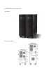
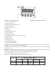
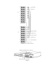
K 6K/10K Diagram 1: Rear Panel Overview Diagram 2: Input/Output Terminal 1. RS-232 communication port 2. USB communication port 3. Emergency power off (EPO) connector 4. Parallel connection port 5. Parallel port intelligent slot 6. Charger fan 7. Power stage fan 8. Maintenance bypass switch 9. Input circuit breaker 10. Isolation transformer fan 11. Input/Output terminal (Refer to diagram 2 for details) 12. Output terminal 1 13. Output terminal 2 14. Utility input terminal 15.
Diagram 1: Rear Panel Overview Note 1: The cable for 6K should be able to withstand currents of over 40A. It is recommended to use a 10AWG or thicker wire for safety and efficiency. Note 2: The cable for 10K/ should be able to withstand currents of over 63A. It is recommended to use an 8AWG or thicker wire for safety and efficiency. Note 3: For single model, it is not necessary to connect the non-isolated neutral terminal.
2-4. Output configuration Option 1: L1 N1 L2 N2 L N To Load 1 To Load 2 There are 2 sets of low-voltage outputs (104/110/115/120V) on L1-N1 & L2-N2. Each set is able to provide 50% of the UPS rated current. Connect one load to L1-N1 and the other load to L2-N2. Option 2: L1 N1 L2 N2 L N To Load After connecting L1&L2 and N1&N2, it becomes one low-voltage output (104/110/115/120V) at L1-N1 for 100% of the UPS rated current. Connect load to L1-N1 or L2-N2.
Option 4: L1 N1 L2 N2 L N To Load 1 To Load 2 To Load 3 After connecting N1&L2, it becomes three outputs, one high-voltage output (208/220/230/240V) at L1-N2 and two lowvoltage outputs (104/110/115/120V) at L1-N1 & L2-N2. However, there is a limit for current rating at L1-N1 & L2-N2: 25A for 6Kmodel and 42A at 10K model. You must connect the load taking into account such limits. Please read the notes before installation.
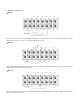
N L Input Line L N L Output 2 Line N Output 1 Neutral L Output 1 Line N Output 2 Neutral Non-isolated Neutral N UPS2 L N N N L N UPS1 N Input Neutral Diagram 1: Power cable connections Parallel communication port connection Share current cable connection Diagram 2
Parallel communication and parallel current connections. 2-6. ForzaTracker monitoring software ForzaTracker is a new generation of UPS monitoring software, which provides user-friendly interface to monitor and control your Uninterruptible Power System. This unique software provides safe auto-shutdown for multi-computer systems during power failures. With this software, users can monitor and control any UPS on the same LAN no matter how far they might be from the UPS.
3-2. LED Indicators and LCD Panel There are 4 LEDs on front panel to show the UPS working status: Mode LED Bypass Line UPS startup Bypass mode AC mode Battery mode CVCF mode Battery Test ECO mode Fault Note: • means LED is illuminated LCD panel: means LED is not illuminated.
Display Function Backup time information Provides a digital indication of the battery discharge time. H: hours, M: minutes, S: seconds Fault information Indicates that a warning or fault has occurred. Displays the fault codes, listed in detail in the sections below. Mute operation Indicates that the UPS alarm has been disabled. Output & battery voltage information Provides an indication of the output voltage, frequency or battery voltage.
3-3.
2) Press and hold the ON button for 0.5 second to power on the UPS. The buzzer will beep once. 3) After a few seconds, the UPS will enter into the AC mode. In case of abnormal utility power, the UPS will transfer to battery mode operation to provide uninterrupted power to the outlets. Note: In battery mode, the UPS will shut down automatically when the remaining charge is low. Once the utility power is restored, the UPS will restart automatically in AC mode. 2.
6. Testing the batteries 1) To check the battery status when the UPS is running in AC mode/CVCF mode/ECO mode, press the Test button to initiate the self-test. 2) To maintain the system reliability, the UPS will perform the battery self-test automatically on a periodic basis. The default setting for the battery self test is once per week. 3) Battery self-test interval can also be set through the monitoring software.
5) Switch on the input breaker and the UPS will enter Bypass mode. If the UPS is in maintenance Bypass mode, turn the maintenance switch to the “UPS” position before turning on the system. 3-5. Parallel operation 1. Parallel system connection 1) Make sure all of the UPSs are designed for parallel operation and that all the wiring is done properly. 2) Turn off the input and output breakers of each UPS. 3) Remove all the maintenance bypass covers and change the maintenance switches from UPS to BPS.
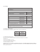
3-6. Abbreviations on the LCD display Abbreviation Display content Meaning ENA Enable DIS Disable ATO Auto BAT Battery NCF Normal mode (not CVCF mode) CF CVCF mode SUB Subtract ADD Add ON On OFF Off FBD Not allowed OPN Allow RES Reserved PAR Parallel 3-7. UPS parameter settings Three parameters need to be configured in order to set up the UPS. Refer to following diagram. Parameter 1 Parameter 1: it is used for the different configuration options.
List of the 15 programs for parameter 1: Code Description Bypass AC ECO Battery CVCF Battery test 01 Output voltage Y 02 Output frequency Y 03 Voltage range for bypass Y 04 Frequency range for bypass Y 05 ECO mode enable/disable Y 06 Voltage range for ECO mode Y 07 ECO mode frequency range setting Y 08 Bypass mode setting Y Y 09 Battery backup time setting Y Y Y Y Y Y 10 Reserved /Programmable output setting** Y Y Y Y Y Y 11 Reserved /Shutdown point for progra
02: Output frequency settings Interface 60 Hz, CVCF mode 50 Hz, Normal mode ATO Setting Parameter 2: Output frequency To set the output frequency, choose any of the following three options in parameter 2: 50.0Hz: The output frequency is set to 50.0Hz. 60.0Hz: The output frequency is set to 60.0Hz. ATO: When selected, the output frequency will be set according to the latest normal utility frequency. If it ranges from 46Hz to 54Hz, the output frequency will be 50.0Hz.
04: Frequency range for bypass Interface Setting Parameter 2: Sets the acceptable low frequency for bypass operation. 50 Hz system: Setting ranges from 46.0Hz to 49.0Hz. 60 Hz system: Setting ranges from 56.0Hz to 59.0Hz. The default value is 46.0Hz/56.0Hz. Parameter 3: Sets the acceptable high frequency for bypass operation. 50 Hz: Setting ranges from 51.0Hz to 54.0 Hz. 60 Hz: Setting ranges from 61.0Hz to 64.0Hz. The default value is 54.0Hz/64.0Hz.
08: Bypass mode setting Interface Setting Parameter 2: OPN: Bypass allowed. When selected, the UPS will operate in Bypass mode depending on the enable/disable bypass setting. FBD: Bypass not allowed. When selected, the UPS will not be able to operate in Bypass mode under any circumstances. Parameter 3: ENA: Bypass enabled. When selected, it means that the Bypass mode is activated. DIS: Bypass disabled. When selected, the automatic bypass may be used, but manual bypass is never allowed.
10: Reserved/ Programmable output setting Interface Setting “Reserved” will be displayed if the UPS is equipped with output transformer ratio of 2:1. The following setting is only available for the UPS with output transformer ratio of 1:1. Parameter 3: Sets the programmable output. You may choose the following three options: ON: Programmable output is manually switched on permanently. OFF: Programmable output is manually switched off.
12: Hot standby function enable/disable Interface Setting Parameter 2: HS.H Enables or disables the Hot standby function. You may choose one of the following two options in Parameter 3: YES: Hot standby function is enabled. It means that the current UPS is set to hot standby, and it will restart once electricity is reestablished, even without having a battery connected. NO: Hot standby function is disabled. The UPS is operating in normal mode and cannot restart without battery.
3-8. Operating mode/Status description When parallel UPS systems are successfully set up, an additional screen with “PAR” in parameter 2 will be displayed and assigned a number in parameter 3, as shown below. The master UPS will be assigned “001” as default, while the slave UPSs will be identified as either “002” or “003”. The assigned numbers may be changed dynamically during operation.
Operating mode/status Description When the input voltage is within an acceptable range, the UPS will provide pure and stable AC power to the output. The UPS will also charge the battery in AC mode. AC mode LCD display Description When the input voltage is within the voltage regulation range and ECO mode is enabled, the UPS will bypass voltage to output for energy saving.
3-9.
4. Troubleshooting guide If the UPS system does not operate correctly, use the table below to troubleshoot the problem. Symptom Possible cause Remedy Even when utility power is normal, The AC input cable is there is no indication on the front not properly connected. panel and the alarm has gone off. Check to make sure the power cord is firmly connected to the AC mains outlet. The icon and the warning code flash on the LCD display, EPO function is enabled. and the alarm starts beeping once every second.
3-9. Fault codes Symptom Possible cause The and icons become illuminated on the LCD display, and the alarm starts beeping once every second Fan is locked or has stopped working; or the UPS temperature is too high. The icon along with warning Parallel communication code becomes illuminated on cable is loose or incorrect the LCD display, and the alarm parallel operation. starts beeping once every second. Remedy Check fans and notify dealer.
Verify that no voltage between the battery terminals and the ground is present before maintenance or repair. In this product, the battery circuit is not isolated from the input voltage. Hazardous voltages may occur between the battery terminals and the ground. A battery can present a risk of electric shock and high short circuit current. The following precaution should be observed when working on batteries: - remove watches, rings or other metal objects. - use tools with insulated handles.
6. Technical specifications Model CAPACITY* FDC-006K FDC-010K 6000 VA / 4800 W 10000 VA / 8000 W INPUT Voltage range Low line transfer 110 VAC ± 3 % at 50% Load 176 VAC ± 3 % at 100% Load Low line comeback High line transfer Low line transfer voltage + 10V 300 VAC ± 3 % High line comeback High line transfer voltage - 10V 46Hz ~ 54 Hz @ 50Hz system 56Hz ~ 64 Hz @ 60Hz system Single phase with ground ≥ 0.
* Derate capacity to 50% of capacity in CVCF mode and to 90% when the output voltage is adjusted to 208VAC. ** If the UPS is installed or used in a place where the altitude is above than 1000m, the output power must be derated one percent per 100m. ***Product specifications are subject to change without further notice.