User Manual Indoor FHD IP Camera Model: R2/R4/R2C/R2E V2.
Table of Contents Security Warning........................................................................................................................................................ 1 1 Overview.................................................................................................................................................................. 1 1.1 Key Features....................................................................................................................................
Security Warning 1. Please change the password of your camera regularly, using a combination of numbers, letters and special characters. 2. We recommend that you regularly update your camera to the latest available software and firmware versions to help ensure the best experience for your camera. 1 Overview FOSCAM Indoor FHD IP Camera is an integrated wireless IP Camera with a color CMOS sensor which enable to view in High Definition resolution.
Support image snapshot Support dual-stream Support SD Card storage up to 128GB Support IR-Cut auto switch Embedded free FOSCAM DDNS(dynamic domain name service) Service Supporting the Third Party Domain Name Service Support two-way audio Support ONVIF protocols Multi-level users management with password protection Motion detection alert via email or upload image to FTP Provide free Android and iPhone APP for viewing live video provide free Central Management Software to manage
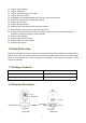
Front panel: LENS: Fixed focus lens. Infrared LED: Infrared LEDs for night vision. Microphone: Built-in microphone. Micro SD Card slot: Supports up to 64GB SD card for storing the video. WPS/Reset WPS: Push both WPS/Reset button on the camera and wireless router within 1 minute, the camera will connect to the wireless router automatically, in WPS process, the Network light will blink every 0.
2 Access the IP Camera 2.1 Wired Connection 1. Mount the antenna and make it stand vertically. 2. Connect the camera to the LAN network (Router or Switch) via network cable. 3. Connect the power adapter to the camera. 4. Visit Foscam official website http://www.foscam.
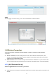
NOTE: When logging in for the first time, you will need to download and install the add-on. 2.2 Wireless Connection There are some ways of wireless connection: EZLink connection, soft AP connection and WPS connection. EZLink connection: Use the mobile phones or other mobile devices to download APP, then connect the camera and the wireless router by the APP. The procedure of the EZLink connection, please refer to the Quick Setup Guide.
WPS button on the wireless router is typically located on the front panel or rear panel.TP-LINK router's WPS button is called QSS (Quick Security Setup). Make sure that the ethernet cable and the camera is disconnected. WPS Button (1) Press and hold the WPS button for three seconds. The Network light of the camera begins to twinkle at high frequency. (every 0.4 seconds) (2) Press and hold the WPS button for three seconds on your wireless router within 60 seconds.
2.3.2 Remote Access If you want to access your camera by web browser outside of your LAN, you need to configure following configurations. 1. Choose “Settings” on the top of the camera web page, then go to the “Network > IP Configuration” section on the left side of the screen, then uncheck the Obtain IP DHCP. IP Address: Set this in the same subnet as your computer , or keep it as default. Subnet Mask: Keep it as default. Gateway and DNS Server: Set it to the IP address of your router. 2.
Click Enable DDNS and click Save. The content in the Manufacture’s DDNS column is the domain name of your camera. 3. You can see the port of your camera here. If you want to set Remote Access for several cameras on the same network, you will need to change the HTTPS port for each camera. 4. If the UPnP of the router has been enable, you do not need to perform following steps. Otherwise, you need to select one of the following methods to configure port forwarding on your router.
Click Add New. Input the port and IP address of your camera and click Save. Here you have finished the Port Forwarding setup. 5. Now you can access your IP camera by https://domain name: HTTPS port via the Internet. 2.4 Using the VLC player The camera supports RTSP streaming, here you can view the camera by VLC player. RTSP URL rtsp:// [user name][:password]@IP:Port number/videostream The part in the square brackets can be omitted.
otherwise, you must only use http port number. Video stream: Three modes are supported: video Main, video Sub and audio. Video Sub is a better choice in bad network condition. If you select audio, you can only hear sound without seeing picture. For example: IP: 192.168.1.11 RTSP Port number: 554 User name: admin Password: 123 Enter either one of the following four URLs in the VLC 1.rtsp://admin:123@192.168.1.11:554/videoMain 2.rtsp:// @192.168.1.11:554/videoMain 3.rtsp://:123@192.168.1.
Sometimes you may need to enter the user name and password for another time. Click OK and you can see the real-time preview.
If you cannot play the video in the VLC player, please check the port mapping. NOTE: If you modify the camera’s username or password, you had better reboot the camera to apply the new username and password in authentication in the VLC. 2.5 IP camera connection to the server Device supports ONVIF 2.2.1 protocol, You can easily access NVR with ONVIF or server with ONVIF.
3 Surveillance Software GUI Please refer to the section 2.1 if you install the camera for the first time. You can start to learn about software operation in the computer. 3.1 login Window Section1 Enter the Username and password The default administrator username is “admin” with no password, please change the password the first time you use and prevent unauthorized users login the camera. Section2 Stream The camera supports two stream modes: Main stream and sub stream.
3.2 Setup Wizard You will go to “Setup Wizard”automatically after your first-login, where you can set the basic parameters of camera, such as camera name, camera time, wireless settings, IP configuration. 3.
: Path to surveillance window. Click this button to go back to the surveillance window : Path to Administrator Control Panel, Click it, to go to Administrator Control Panel and do advanced settings. : Click this button to go back to the Playback panel to view the stored audio files stored in the SD Card. Section 2 Multi-Device Window The firmware inside the camera supports up to 9 cameras being monitored at the same time. You can add other cameras in multi-device setting.
NAA NAA(Network Auto-Adaptability) can make IP camera change the real-time rate to adapt different network conditions. It can supply better preview experience. The default NAA setting is off. “Zoom in” or ”Zoom out” Click or ,The focal length of the camera lens will be larger or shrink, you can adjust the focus distance to the target object size, access to high-definition screen. Note: R2C don’t support this zoom feature.
Horizontal: The camera will rotate from left to right. : Start cruise. : Stop cruise. If you want to define or change the cruise trace, please go to Settings PTZ Preset Settings panel. How to do cruise? Firstly: Select one track in the track dropdown list. Select one of these. Secondly: Click Start cruise button, the camera will cruise following the predefined path. Thirdly: Click stop button and finish cruising.
If you want to see one preset position you have set, only select the preset position name from the preset drop-down list, and click go button, the camera will go to the preset position. Section 5 IR LED Lights / Color Adjustment Click Infra led and there are three modes to adjust the infrared led: Auto, Manual and Schedule. Auto: Select it and the camera will adjust the infra led (on or off) automatically. Manual: Select it and you can turn on or turn off the infra led manually.
4----- Audio Click this icon, the icon will become to you can hear the sound around the camera by the earphone or speakers that connected with PC. 5----- Adjusting the sound Click this icon, the icon will become to ,you can change the sound of the camera. 6----- Snapshot Click it to make snapshot and it pop-up a window which picture you snapshot, right click in the window and save the picture to anywhere you want.
When you select the Full Screen, then click right mouse, there is a Screen PTZ button. Click the Screen PTZ button and put the mouse on the screen to indicate the camera move direction you prefer, press the left mouse, the camera will move to the corresponding direction. Loosen the mouse and stop moving. Press Esc button or double click right mouse and cancel the function. NOTE: For Mac OS, the plugin cannot support Onscreen Mouse Control, so you cannot allow to use it.
4 Advanced Camera Settings Click the button “Settings”, goes to Administrator Control Panel to make advanced camera settings. 4.1 Setup Wizard Please go to section 3.2 to find the way to set it. 4.2 Status Status contains four columns: Device Information, Device Status, Session Status and Log, it will show you various information about your camera. 4.2.1 Device Information Camera Model: The camera model NO.
and so on. 4.2.3 Session Status Session status will display who and which IP is visiting the camera now. 4.2.4 Log The log record shows who and which IP address accessed or logout the camera.
Reboot the camera and clear the log records. 4.3 Basic Settings This section allows you to configure your camera’s Name, Time, Mail, User account and Multi-Device. 4.3.1 Camera Name You can define a name for your camera here such as apple. Click Save to save your changes. The alias name cannot contain special characters. 4.3.2 Camera Time This section allows you to configure the settings of the internal system clocks for your camera.
Time Zone: Select the time zone for your region from the dropdown menu. Sync with NTP server: Network Time Protocol will synchronize your camera with an Internet time server. Choose the one that is closest to your camera. Sync with PC: Select this option to synchronize the date and time of the Network Camera with your computer. Manually: The administrator can enter the date and time manually. Note select the date and time format. use DST: Select the daylight saving time from the dropdown list.
How to change the password? Firstly, select the account which you want to change the password, then select “Change password”, enter the old password and the new password, lastly click modify to take effect. How to add account ? Select one blank column, then enter the new user name, password and privilege, last click Add to take effect. You can see the new added account on the Account list.
Delete :Select the account which you want to delete, then click Delete button to take effect. NOTE: The default admin account cannot be deleted, but you can add other administrator users. How to change the username ? Firstly, select the account which you want to change the username, then select “Change username”, enter the new password, lastly click modify to take effect.
4.3.4 Multi-Camera If you want to view multi-surveillance screens on one window, you need to login one camera, and set it as the main device, and do Multi-Device Settings, add other cameras to the first one camera. Before you do multi-cams settings, you need to assign different port such as 81, 82, 83, 84, 85, 86, 87, 88 to the cameras if there is 8 cams installed. The firmware within the camera can support a maximum of 9 devices monitoring all at the same time.
1 Click it, camera model, alias, host and HTTP Port will be filled in the following boxes automatically. 2 Enter the User name and password of the 2nd camera. 3 Click Add to take effect. Camera Model: Our Company produces two series cameras: MJPEG and H.264. Here will show you which series the camera belongs to.
Back to Surveillance Windows, and click Four Windows option, you will see four cameras you added. Add cameras in WAN If you want to view all cameras via the internet(remote computer), you will need to add them using DDNS domain name. Firstly, make sure all of the cameras you added can be accessed through the internet. (The way to configure DDNS is in chapter 4.4.4) Login to the first camera using a DDNS domain name and port.
Use DDNS domain name and port to login Make sure each camera you need add could login with DDNS name and port. Click Multi-Device Settings. Choose The 2nd Device. Fill in the 2nd camera’s name, DDNS domain name, port number. Enter user name and password and then choose Add. 1 ---- The camera model: MJ or H264. 2 ---- The 2nd camera’s name 3 ---- Fill in the 2nd camera’s DDNS host not LAN IP NOTE: The MJ series have the same HTTP Port NO. and Media Port NO.
Return to video window. You will see all of the cameras accessible through the internet. When you are away from home, you can use the first camera’s DDNS domain name and port to view all the cameras via internet. 4.3.5 Status Light You can enable or disable status light.
4.3.6 Voice Prompt On this page, you can enable or disable voice prompt. Select “Yes” to enable or select “No” to disable. 4.4 Network This section will allow you to configure your camera’s IP, DDNS, Wireless Settings, UPnP and Port. 4.4.1 IP Configuration If you want to set a static IP for the camera, please go to IP Configuration page. Keep the camera in the same subnet of your router or computer. Changing settings here is the same as using the Equipment Search Tool.
Set the same Subnet Mask and gateway of the camera with your PC. There are two DNS servers. You can set any of them. Same with gateway is also OK. If you don’t know the DNS server, you can use the same settings as the Default Gateway. 4.4.2 Wireless Settings Step 1: Choose “Settings” on the top of the camera interface, and go to the “Network” panel on the left side of the screen, then click “Wireless Settings.
Click the Scan button and the camera will detect all wireless networks around the area. It should also display your router in the list. Click the Scan button to search for wireless networks. Click the Page number to see other wireless networks devices if there are more than 10. Step 2: Click the SSID (name of your router) in the list, the corresponding information related to your network, such as the name and the encryption, will be filled into the relevant fields automatically.
Step 3: Please click on the Save button after all settings have been entered and disconnect the network cable. Never shut down the power of the camera until the IP camera is able to connect to the wireless network. The LAN IP address will disappear on the window of Equipment Search Tool when the camera is configuring a wireless connection. Wait about 1 minute, the camera should obtain a wireless connection, and the LAN IP of the camera will show again on the window of the Equipment Search Tool.
If you don’t have a Foscam Cloud account, click “Tap HERE” to register one, then click “Get DDNS”.
After get DDNS, click “Finish” to go back to DDNS settings. If the network error, you fail to get the DDNS, please try again.
Once you success get Foscam DDNS, you can follow below step to use. Here take test09.myfoscam.org for example. Go to option of DDNS on the Settings->Network panel, you can see the domain name. Now you can use http:// Domain name + HTTP Port to access the camera via internet. Take hostname test09.myfoscam.org and HTTP Port no. 800 for example, the accessing link of the camera via internet would be http:// test09.myfoscam.
Restore DDNS to factory: If you have configured Third Party DDNS successfully, but you want to use Manufacturer’s DDNS again , here click this button and start Manufacturer’s DDNS Service. User can also use third part DDNS, such as www.no-ip.com. ,www. 3322.com 4.4.4 UPnP The default UPnP status is closed. You can enable UPnP, then the camera’s software will be configured for port forwarding.
4.4.5 Port This camera supports HTTP Port. HTTP Port is used to access the camera remotely. If you want to access the camera and view the video, the HTTP Port must both be configured correctly. HTTP port: By default, the HTTP is set to 88. Also, they can be assigned with another port number between 1 and 65535. But make sure they can not be conflict with other existing ports like 25, 21. Another way to change the HTTP port NO.
Step 2: Enter the username and password of the Administrator (default username is admin with a blank password), and click “OK” to apply changes. Step 3: Wait around 10 seconds, you’ll see that the camera’s LAN IP address has changed. In our example it was changed to 2000, so we see http://192.168.1.110:2000 in Equipment Search Tool. Also, the LAN IP address is now fixed at a static IP address of http://192.168.1.110:2000.
1---- SMTP Server/ Port /Transport Layer Security Enter SMTP server for sender. SMTP port is usually set as 25. Some SMTP servers have their own port, such as 587 or 465, and Transport Layer Security usually is None. If you use Gmail, Transport Layer Security must be set to TLS or STARTTLS and SMTP Port must be set to 465 or 25 or 587, which port you choose should be decided by which Transport Layer Security you select.
If the test success, you can see the Success behind the Test, at the same time the receivers will receive a test mail. If the test fails with one of the following errors after clicking Test, verify that the information you entered is correct and again select Test . 1) Cannot connect to the server 2) Network Error. Please try later 3) Server Error 4) Incorrect user or password 5) The sender is denied by the server.
Figure a Figure b FTP server: If your FTP server is located on the LAN, you can set as Figure a. If you have an FTP server which you can access on the internet, you can set as Figure b. Port: Default is port 21. If changed, external FTP client program must change the server connection port accordingly. FTP Mode: Here supports two modes: PORT and PASV. Username/password: The FTP account and password. Click Save to take effect. Click Test to see if FTP has been successfully configured. 4.4.
Foscam App named Foscam on App Store and Google Play for iOS and Android devices. NOTE: If the QR code scanning is not successful, please input the UID on the bottom of the camera manually. 4.5 Video This section allows you to configure Video stream settings, On screen display and Snapshot settings. 4.5.1 Video Settings There are two ways to set the stream video settings. They are main stream video settings and sub stream video settings.
is very narrow, and bit rate is large, that will lead to video can not play well. The Equilibrium Model is a value between HD Mode and Smooth Mode. Resolution: The camera supports multiple types, For example: 960P, 720P, VGA. The higher the resolution is the clearer video will become. But the code flux will become larger too, and it will take up more bandwidth. (The maximum frame rate for each model is different, please see the “Specifications”.
This page is used to set some mask as privacy zone on the video. Allow On Screen Display Mask There are two options: Yes or NO. Select yes and draw up to four mask areas on the video, the mask area will be black on the video. The mask area. Click OK button and return to the OSD page, click Save to take effect.
4.5.4 Snapshot Settings On this page you can set the snapshot pictures’ image quality and the storage path. Manual snap Quality: Low, Middle and High. The higher the quality, the picture will be clearer. Pictures Save To: FTP or SD card. If you have done FTP and Alarm settings, when alarming, the camera will snap pictures to the FTP or SD card automatically.
2 Capture interval:The interval time between two captures. 3 Select the capture time Capture anytime Click the black button up the MON, you will see all time range turn red. When something moving in the detection area at anytime, the camera will capture. Specify an capture schedule Click the week day words, the corresponding column will be selected. For example, click TUE, the all column of TUE turns to red, that means during Tuesday whole day, the camera will capture.
Step 1: Enable motion detection function. Step 2: Sensitivity---- It supports five modes: Lowest, Lower, Low, Medium and High. The higher the sensitivity, the camera will be more easily alarmed. Select one motion sensitivity. Step 3: Trigger interval--- The interval time between two motion detection.
If you select this checkbox, when the motion has been detected, the camera will record automatically and store the record files to the SD Card. Make sure the camera has inserted SD card and you have set the SD card as the Alarm record files storage path, please go to Record—> Storage location page to verify this settings. The default alarm record time is 30s and pre-alarm record time is 5s, please go to Record—> Alarm Record page and change the alarm time settings.
③ Press the left mouse and drag it on the time boxes, you can select the serial area. Step 7: Click Save button to take effect. When the motion has been detected during the detection time in the detection area, the camera will alarm and adopt the corresponding alarm indicators. NOTE: You must set the detection area and detection schedule, or else there is no alarm anywhere and anytime. 4.6.2 Sound Detection When the ambient sound over a certain decibel ,the sound alarm will be triggered.
If the Sensitivity is set to “Low”, the camera will detect the sound whose more than 75db. If the Sensitivity is set to “Lower”, the camera will detect the sound whose more than 85db. If the Sensitivity is set to “Lowest”, the camera will detect the sound whose more than 95db. 4.7 Record This section will allow you to change the record files storage path and the record time. 4.7.1 Storage Location On this page you can change the alarm and manually recording storage path.
4.7.4 Schedule Recording When the video is selected as FTP, the device supports scheduled recording. When the parameter Recording Location is set SD Card on the Storage Location page, you can configure parameters as shown in follow figure.
When the video is selected as SD card, the device supports pumping frame recording. When the parameter Recording Location is set SD Card on the Storage Location page, you can configure parameters as shown in follow figure. Record full strategy: When the SD card is full, you can choose to cover the previous recording, or stop recording. Audio Record: You can choose "yes" or "no". NOTES: Scheduled recording only supports video saved to the SD card or FTP server.
You can refer to "alarm schedule." in "Alarm" about editing the time of recording Schedule. 4.7.5 SD Card Management This camera supports SD Card. When you plug in the SD card during the camera work process, please reboot the camera again, or else the SD Card may be cannot work well. The default storage path of alarm record files is SD card, when the available size of SD card is less than 256M, the old record files will be deleted automatically.
4.8.2 Cruise Settings This section explains how to add/ delete/ alter one cruise track. Setting the Cruise Mode There are two cruise mode: Cruise time and Cruise Loops. Cruise time: Select Cruise time from Cruise Mode drop-down, then you can set the Cruise time of the camera. Cruise Loops:Select Cruise Loops from Cruise Mode drop-down, you can set the Cruise Loops of the camera. Click Save to take effect.
Manage the Cruise Track There are two default cruise tracks: Vertical and Horizontal. Vertical: The camera will rotate from up to down Horizontal: The camera will rotate form left to right. Add: Add one cruise track, then click save button. Delete: Select one cruise track and delete it. Save: After you modify the Dwell time, you should click Save button to take effect. Example How to do add cruise tracks ? Firstly, Click Add button and enter a descriptive name to identify the cruise track.
Thirdly: Click OK button and the cruise track will take effect. You can add other cruise track as the same method. For example: I have added three preset points to the “track 1”, that means : When I select the “track 1” on the surveillance window, the camera moves as the following track: upright then Right Most last down left. You can add preset on the left of the surveillance window. Add the preset. The cruise tracks have added to the “track 1”.
There are other buttons between the Preset points and Cruise track, you can use these buttons to adjust the order of preset points or add/delete one preset points in one cruise track. Add: Select one preset points and add it to the selected cruise track. Delete: Select one preset points you have added to one cruise track, click delete. Move up/ down: Select one cruise track, adjust the order of preset points in one cruise track.
4.9 Firewall This section explains how to control the access permission by checking the client PC’s IP addresses. It is composed of the following columns: Block access from these IP addresses and Only allow access from these IP addresses. Enable firewall, If you select Only allow access from these IP addresses and fill in 8 IP addresses at most, only those clients whose IP addresses listed in the Only allow access from these IP addresses can access the Network Camera.
parameters. 4.10.2 System Upgrade Click “Download the latest firmware”, you will see the following screen. And click “save” to save the firmware on your computer locally. Your current firmware version will be displayed on your screen. You may go to the Status Device Information page to check for the latest firmware versions available. Click Browse, choose the correct bin file and then click System upgrade. Don’t shut down the power during upgrade. After upgrading, you can see the upgrade result.
Upgrade Firmware by Equipment Search Tool Double click the Equipment Search Tool shot icon , select the Camera IP that you want to upgrade the firmware. Then select Upgrade Firmware and enter the username and password, choose the firmware file, and upgrade. Figure 4.1 CAUTION: We recommend that you regularly update your camera to the latest available software and firmware versions to help ensure the best experience for your camera.
NOTES: Please ensure you have download the correct firmware package for your camera before upgrading. Read the upgrade documentation (readme.txt file) in the upgrade package before you upgrade. Upon downloading the firmware check the sizes of the .bin files. They must match the size in the readme.txt file. If not, please download the firmware again until the sizes are the same. Your camera will not function correctly if a corrupt .bin file is used.
5 Playback On this page you can view the record files stored in the SD card. Section 1 Define the Record files time and Type : The storage path of record files : Here supports three types: current day, current month and All records. Another way, select the time on the time&date manually. : The type of records files, Here supports two typs: Normal record, Alarm record and All records. : Click this button to search all record files satisfy the conditions you selected.
Section 2 Search record files On this panel you can see all record files satisfy the conditions you set. Section 3 Play/Stop/Audio/Full screen buttons Please select one record file before use these buttons. Click this button to play the record files Click this button to stop the record files Open or stop audio Click this button to make full screen, and double click left mouse to exit full screen.
6 Appendix 6.1 Frequently Asked Questions NOTE: Any questions you would meet, please check Network connections firstly. Check the working status revealed by the indicators on the network server, hub, and exchange. If abnormal, check the network connections. 6.1.1 Equipment search tool cannot find the camera After power on camera and connect it to router by Ethernet cable, open Equipment Search Tool it cannot find any camera IP address. Shows a blank window like below.
6.1.2 Install plugin for Internet Explore Suggest use IE browser to log in the camera and install the plugin for the first time, then you can use it on other browser as well. Just remember to allow the plugin to run. See below for steps to install plugin via IE browser. Step 1: User IE browser to log in the camera for the first time, it will prompt to ask your install the plugin on the bottom of IE browser. Step 2: Click Install to continue the installation of the .exe plugin.
Step 4: Click Finish and reboot IE browser to log in the camera. Note, for Safari on MAC OSX it’ll show a link “Plugins are not found, click me to download” just above login windows of the camera. Please click it to download plugin and follow wizard to install. See this link for help if after installed plugin but still cannot login camera: http://www.foscam.com/faqs/view.html?id=14 6.1.
Step1: Please make sure wireless signal is strong enough to connect with. (1) Make sure the camera antenna is fixed well; (2) Best to keep the distance between the camera and router in 2~3 meters while setup; (3) There’s no interference or obstacles from house appliance or walls; Step2: Please check if the frequency band of the wireless signal is 2.4GHz. Our cameras only support connecting to 2.4GHz frequency wireless band. If your wireless router is dual band, that supports two frequency band 2.
Go to camera Status > Device Status menu, and you can check if camera’s DDNS is successful. For the case DDNS shows failed, please follow below tips to help it synchronize: (1) Change DNS server to 8.8.8.8. Please login camera’s web-page, and go to the IP configuration (For HD cameras) or basic network settings (For SD cameras) menu to make the change. (2) Reboot the camera and router, wait a few minutes to check again. (3) Use a 3rd party DDNS instead, like No-IP, to see if it works. 6.1.
Note: 1) Please DO NOT forget to set the alarm schedule, the alarm schedule is red. 2) Please make sure your camera time is correct. 3) Please DO NOT forget to set the alarm area, the detected area is covered by the red grids. Or for some models you can setup 3 detection zones in total. Step 2: Setup the Storage Location Go to Settings > Record > Storage Location, and set the “Recording Location” to “SD card and click Save.
Note: (1) Please make sure that your sender email supports SMTP; (2) Please click on Save before you click on Test; (3) Make sure the test result is success. (4) After succeed, you will receive a test email in the mailbox of Sender. Step 2: Setup the Motion Alarm Settings Please go to Settings > Alarm > Motion Detection menu: 1. Click enable, 2. Choose Send E-mail for the alarm action, 3. set your detection area, 4. Set your schedule.
Do not forget to click on Save after you finish settings. If there is motion trigger, camera will alarm and you can receive alarm emails. Note: (1) Please DO NOT forget to set the alarm schedule, the alarm schedule is red. (2) Please make sure your camera time is correct. (3) Please DO NOT forget to set the alarm area, the detected area is covered by the red grids. Or for some models you can setup 3 detection zones in total. 6.1.
(2) Power off the camera then power back on, (3) Delete camera from app then re-add it back, also lower camera’s resolution. 6.1.10 Camera is added by others When use myfoscam.com cloud or Foscam app, one camera can only be added to one account at the same time. To solve error “This camera has already been added by another account” when add camera to Foscam app or cloud, please send a clear photo of camera’s model sticker to Foscam support email support@foscam.com to unbind it.
Flip image flip and mirror Infrared mode Automatic or manual manual Pan/Tilt Angle Horizontal:350° & Vertical: 100° Supports two-way audio Audio Input/Output Built-in Mic & Speaker Audio Compression PCM/G.726 Ethernet One 10/100Mbps RJ45 port Wireless Standard IEEE802.11b/g/n IEEE802.11b: 11Mbps(Max.); Data Rate Network IEEE802.11g: 54Mbps(Max.); IEEE802.11n: 150Mbps(Max.).
Lens Min. Illumination 0 Lux (With IR Illuminator) Lens Type f:4.0mm,F:2.1 Angle of View Horizontal:67° Diagonal : 75° Night Vision 13pcs IR-LEDs, IR Range up to 8m(26ft) Image Compression H.264 2560x1440 (4.0 Megapixels), Resolution 2304x1296 ( 3.
Physical Environment Dimension(LxWxH) 74x74x119mm(2.9x2.9x4.7in) Net Weight 290g(0.6lb) Operating Temperature -10°C ~ 55° (14°F ~ 131°F) Operating Humidity 20% ~ 85% non-condensing Storage Temperature Storage Humidity Certification Lens 0% ~ 90% non-condensing CE, FCC, RoHS ITEMS Image Sensor -20°C ~ 60° (-4°F ~ 140°F) R2C Sensor Type 1/3'' CMOS Display Resolution 1920 x 1080 (2.0 Megapixels) Frame Rate 30fps Min. Illumination 0 Lux (With IR Illuminator) Lens Type f:2.8mm,F:2.
Other Features Power Physical Motion Detection Alarm via E-Mail, upload alarm snapshot to FTP WDR Improve image clarity in complex scenario User Accounts Three levels user role Firewall Supports IP Filtering Storage 128G Micro SD card, local and FTP storage Reset Reset button is available Alexa Support Alexa Power Supply DC 5V/2.0A Power Consumption <6W Dimension (LxWxH) 74x74x119mm(2.9x2.9x4.7in) Net Weight 290g(0.
the user’s authority to operate this equipment. This equipment complies with FCC radiation exposure limits set forth for an uncontrolled environment. This equipment should be installed and operated with minimum distance 20cm between the radiator& your body. This transmitter must not be co-located or operating in conjunction with any other antenna or transmitter. CE Mark Warning This is a Class B product.
original accessories included such as power adapters, brackets, cables, manuals, and driver CD disks. Write your RMA number and the return reason (the problem of the product) on the warranty card along with the complete package to send them back. Replacement Services If customers ask for replacement service, please contact point-of-purchase and follow their policy. Our technicians will inspect all items returned for replacement requests.
customer’s personal expectation, customers should responsible for both shipping fee. Customers shall be responsible for both shipping fee if their product beyond the replacement limit but still in warranty limit. Repair Service Out Of Warranty FOSCAM provide extra repair service for product that out of warranty, it is chargeable. The total fee contains device cost and service fee. Device cost (including accessories) is the standard uniform price provide by FOSCAM.
system or the Internet network, computer viruses, malicious attacks of hackers, information damage or loss, and faults of computer system. Foscam company does not need to take any responsibility of the special, incidental or corresponding loss by the products of our company or any software provide by our company, including but not limited to operating loss, profit or purpose. The company only takes the responsibility applicable to national and local legal requirements.
7 Obtaining Technical Support While we hope your experience with the IPCAM network camera is enjoyable and easy to use, you may experience some issues or have questions that this User’s Guide has not answered. If you have problem with FOSCAM IP camera, please first contact FOSCAM reseller for solving the problems. If our reseller cannot provide service, please contact our service department: support@foscam.com CE Certificate Website: http://www.foscam.com/company/ce-certificate.