Model:C7 4E -B B BC 01 C7 4E - BB BC 02 Four Burner User Guide
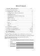
Table of Contents I. Important Safety Information................................................1-4 II. Control Panel Overview..........................................................5 III. Specifications & How to Use................................................6 • Heating Power for Each Cooking Zone.................................6 • Operating the keys ...............................................................7 • Switching on the hob and cooking zones..............................
I. Important Safety Informaton When using electrical appliances,basic safety precautions should always be the Induction cooker, even with the built - in safety features,it is essental to heed all precautons. Installaton of the appliance into a kitchen countertop and its connecton to the main power and electrical supply may only be performed by a qualified technician. While cooking any overflowed fat or oil on the cooktop may ignite .
I.
I. Important Safety Informaton Do Not Cook on Broken Cook-Top – If cook-top should break, cleaning solutions and spillovers may penetrate the broken cook-top and create a risk of electric shock. Contact a qualified technician immediately. Do Not Cook on Broken Cook-Top – If cook-top should break, cleaning solutions and spillovers may penetrate the broken cook-top and create a risk of electric shock. Contact a qualified technician immediately.
I. Important Safety Informaton This product should not be thrown away as household waste . Instead it should be handed over to the applicable collection point for the recycling of electrical and electronic equipment . By ensuring this product is disposed of correctly , you will help prevent potential negative consequences to the environment and human health , which could otherwise be caused by inappropriate waste handling of this product .
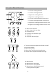
II. Control Panel Overview 1. Left rear cooking e lement 2. Left front cooking e lement 1 3 3. Right rear cooking element 4. Right front cooking element 4 2 6. Left rear cooking element control area 7. Left front cooking element control area 9. Right front cooking element control area 6 7 10 9 10.Right rear cooking element control area 16 12 15 13 11 20 19 14 11. Main Power On/Off 12. Main Power indicator light 13. Controls Lock 14. Control Lock indicator light 15. Stop/Go 16.
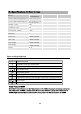
Model C74E-BBBC01 Product dimension ( wxdxh ) inch 23 1/3"x20 1/2"x2 3/16" Cut-out dimension(wxd) inch Min.:18 15/16"x21 15/16" Max.
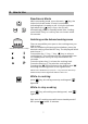
III. How to Use Readiness Mode While on standby mode, press the main “ ” key, the induction hob will make a “beep” sound once indicating that it is ready to use. If only the indicator light above the “ ” key is lit up, the unit will automatically return to standby mode if the Cooking zone ON/OFF key or Lock key are not chosen within 30 seconds. Switching on the hob and cooking zones Suitable for induction cooktop 1 9 P Place a compatible pot or pan on the cooking zone you wish to use.
III. How to Use Lock Activating the Child Safety Lock during cooktop use: Child Lock prevents activation of any sensor key A. Manual: Press the Lock key to activate the function. The unit will make a “beep” sound and the indicator light will turn on above the Lock key. The controls are now locked. Switch off the lock While in Lock mode, press the Lock key to deactivate the function. The indicator light will turn off. Turn off a. Press the ON/OFF key of the cooking zone being used.
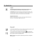
III. How to Use Timer Setting the Timer to Automatic switch-off: With the desired heating zone Powered ON, press the “Timer” key. The timer display will blink and show a “00”, Press the “+” or “-” to increase or decrease to the desired time until the desired time appears in the display (Choose up to 99 minutes). Once the Timer is set, if keys haven't been pressed after 5 seconds, it will begin to countdown, the timer display will remain lit, the indicator for that particular burner will flash.
IV. Compatble Cookware Inducton requires pots and pans that are made of ferrous(meaning magnetc) materials. Check your cookware’s retail box for the inducton symbol. To tell if your current cookware is compatble with the inducton technology, grab a magnet and see if it holds to the botom of the cookware.
V. Cleaning and Maintenance: Cleaning Burned on Residue: WARNING : Damage to the glass surface may occur if you use scrub pads or any other type of abrasive cleaning materials. 1. Allow the cooktop to cool. 2. Spread a few drops of the ceramic cooktop cleaner on the burned residue area. 3. Using the included ceramic cooktop cleaning pad, rub the residue area, applying pressure as needed. 4. If any residue remains,repeat the steps listed above. 5.
VI.Counter Installation Instructions: Warning! For Your Safety:Do not store or use gasoline or other flammable vapors and liquids in the vicinity of this or any other appliance.To eliminate the risk of burns or fire due to overheating,cabinets located above the induction unit should be avoided.If cabinet space is available , the risk can be reduced by installing a range hood that protects horizontally at a minimum of 5 inches below the bottom of the cabinets.
VI.Counter Installation Instructions: Cooktop Dimensions A. Width B. Depth 23-7/32" 20-15/32" C. Height D. Height 5/32" 2-5/32" Cooktop Cutout Dimensions E.Depth F.Depth Minimum:21-31/32" Minimum:18-29/32" Maximum:22-7/16" Maximum:19-7/8" G.Depth Minimum:3-11/32" H. Depth Minimum:13/32" Maximum:25/32" 13 I. Depth J. Depth K. Height L.
VI.Counter Installation Instructions: Before installing the cooktop: 1. Visually inspect the cooktop for damage. Also make sure all cooktop screws are on tight. 2. Place the cooktop into the countertop cutout. Model and Serial Number Locaton: The serial plate is located under the cooktop. When ordering parts or making inquiries about your cooktop, be sure to include the model and serial numbers. Connectng to a 3 wire power supply cable electrical system 1. Disconnect the power supply. 2.
VI.Counter Installation Instructions: Connectng to a 3 wire power supply cable electrical system 3. Circuit breaker fuse ratng must be above 40 A. 4. Minimum acceptable size of conductors should be no less than 10AWG,copper only,and no less than167 F . 5. A wire-binding screw or stud used in the wire terminal should be 10 or larger. Warning! 1. The electrical power to the cooktop must be shut off while line connectons are being made.Failure to do so could result in serious injury or death. 2.
VII.Troubleshooting Error Codes If the display shows an error code,please refer to this sheet for a potential solution. Cooktop does not work Cooktop does not heat up The cooktop features an automatic shut off that turns off the entire cooktop if any of the cooking zones have been on continuously for 2 hours. Cooktop turns off while cooking The cooktop control panel may read liquids or objects obstructing the panel, which can cause the cooktop to shut off.
VII.Troubleshooting Error Codes If the display shows an error code,please refer to this sheet for a potential solution. Error Code “E” appears on the Power display Possible Cause Electronics fault error message of specifc cooking zone. Soluton See E0,E1,E2,E3,E7,E8,E9,EE “E0” appears in the I GB T ov er h e a ti n g . Timer display Turn of unit untl to allow IGBT to cool.Restart unit. No cookware found or improper “E1” appears in the placement of cookware on the Timer display cooking zone.
VIII.FCC STATEMENT: F CC S TA TE ME NT ; Th is de vi ce co mp li es wi th Pa rt 18 of th e F CC Ru le s. NO TE : 1. Th is eq ui pm en t h as be en te st ed an d f ou nd to co mp ly wi th th e l im it s f or a Co ns um er IS M e qu ip me nt , p ur su an t t o P ar t 1 8 o f t he FC C R ul es . T he se li mi ts ar e de si gn ed to pr ov id e r ea so na bl e p ro te ct io n a ga in st ha rm fu l i nt er fe re nc e i n a re si de nt ia l i ns ta ll at io n.