USER'S MANUAL FOR INDUCTION HOBS cod.
Dear customer! The built-in induction cooktop is intended for household use only. Materials used for packaging are nature friendly and may be recycled, deposited or destroyed without any threats to the environment. In order to recognize these features, all packing materials are marked with relevant symbols. Once your appliance has become obsolete and you do not intend to use it any longer, take adequate care not to litter the environment.
IMPORTANT WARNINGS • The appliance may be built-in and connected to the power supply only by a qualified technician. • Particular areas of the cooktop surface (adjacent to the hotplates) are hot during operation. Prevent the children to hang around the appliance and warn them properly against the danger of burns. • Hot oil ignites readily, so be sure have the preparation of such food (fries) under constant control. • Hotplates may not be left in operation empty, without any dishes on top.
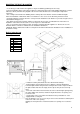
MOUNTING THE BUILT-IN COOKTOP Caution ! • To avoid any possible hazard, the appliance may be installed by qualified personnel only. • Panels and furniture lining of the kitchen cabinet receiving the hob must be treated with temperature resistant adhesives 100°C (otherwise they might be discoloured or deformed because of inadequate temperature resistance). • The cooking hob is intended for building into the worktop above the kitchen element of ≥600 mm depth.
Installation procedure • Worktop must be placed absolutely horizontal. • Suitably protect the edges of the cut aperture. • Connect the cooking hob to the mains power supply (see instructions for the connection of the cooking hob to mains power supply). • Insert the hob into the cut aperture. • Press the hob firmly towards the worktop from above. CONNECTION TO THE POWER SUPPLY • Connections may be carried out by a qualified technician only. The earthing protection must comply with the standing regulations.
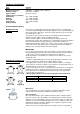
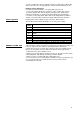
TECNICAL INFORMATION Type Width Electrical connection Working voltage Type of switch Cooking zones ( Ø, mm/W ) Forward left Rear left Rear right Forward right Total power (W) 7372241 590 mm 230-240 V~ or 400-415 V 2N~, 50/60 Hz 230-240 V~, 50/60 Hz Electronic sensors 210 , 1500 (P=2000) 145 , 1200 (P=1600) 210 , 1500 (P=2000) 145 , 1200 (P=1600) 2800 P= extra powerful setting Hotplate function principle Hob surface is completely flat and smooth, without edges to accumulate dirt.
you place smaller dish upon the hotplate and it is recognized, the hotplate will only use the amount of energy required to heat the dish according to its size.
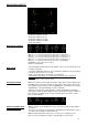
INDUCTION COOKTOP 1.Induction hotplate front left 2.Induction hotplate rear left 3.Induction hotplate rear right 4.Induction hotplate front right 5.Hob control panel Hob control elements A. Keys (+ e -) to increase/decrease power level of cooking zone 1 B. Keys (+ e -) to increase/decrease power level of cooking zone 2 C. Keys (+ e -) to increase/decrease power level of cooking zone 3 D. Keys (+ e -) to increase/decrease power level of cooking zone 4 E.
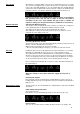
Pan sensor Each burner is complete with its own sensor for detecting the presence of a pan. The system is fine-adjusted to recognize the presence of a pan that, according to the scale of the EN standards, is one size smaller than the nominal diameter of the burner. If the hotplate fails to detect any pan or detects an aluminium pan, power level flashes on its display. After 60 seconds power level backs to 0.
timer can only operate on one heater each time. The heater must always be selected (the display must be viewed “0”) before the time is set; otherwise, the timer will switch off. If we take longer than 10 seconds to select the heater, the timer will switch off. If, after selecting the heater, the time is not defined (T=00) in 5 sec., the timer switches off. When the timer value runs out, the heater associated with the timer switches off.
change the level, the safety mechanism will switch the hotplate off after 10 hours. Protection against overheating Induction cooktop is also fitted with safety device against overheating which protects electronic parts from damages. This device operates on several levels. When cooking zone’s temperature increases excessively, the two-stage fan switches first.
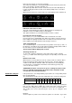
The sequence to set a new Cooktop Power Limit is: ▪ During the first 30 seconds after plugging the appliance ▪ The Touch has to be unlocked and all Heaters Off ▪ Push at the same time (A+,A-,D-,D+) keys ▪ Once this is done, a beep sounds and “Po” Characters will be in the timer display and the “actual Cooktop Power Limit” will be in the display 1 and in the display 4.
Safety functions and error display. ERROR CODE FA ERROR DESCRIPTION Anomaly of infrared signal, of on/off key all cooking zones are deactivated FC Receiver infrared anomaly of button on/off - all cooking zones are deactivated FE Touch control ntc sensor: short circuit on ntc sensor.
zones are deactivated an error is visualised on all displays Opening of NTC - all cooking zones are deactivated an error is visualised on all displays Tension missing on a generator part (right or left) - all cooking zones are deactivated an error is visualised on all displays F4 F6 FOR TECHNICAL ASSISTANCE SPECIFYING THE ERROR CODE CONTACT AUTHORIZED CENTER FOR TECHNICAL ASSISTANCE SPECIFYING THE ERROR CODE CONTACT AUTHORIZED CENTER FOR TECHNICAL ASSISTANCE SPECIFYING THE ERROR CODE CLEANING AND MAINTE
. Foster spa 42041 Brescello (RE) - Italy tel. +39.0522.687425 - tel. Servizio Assistenza +39.0522.684450 fax +39.0522.686019 - fax Servizio Ricambi +39.0522.962166 e-mail: service@fosterspa.com www.fosterspa.