USER'S MANUAL FOR GAS COOKER HOBS cod. 9606801 Abstract Foster spa via M.S. Ottone, 18/20 42041 Brescello (RE) - Italy tel. +39.0522.687425 - tel. Servizio Assistenza +39.0522.684450 fax +39.0522.686019 - fax Servizio Ricambi +39.0522.962166 e-mail: service@fosterspa.com www.fosterspa.
ENGLISH Dear Customer, We thank you for having chosen a Foster cooker hob. Your preference is our pride and satisfaction. In this document are the recommendations and instructions that will enable you to make the best use of the purchased cooker hob and guarantee its best preservation in time. We ask that you take a few minutes to protect the efficiency of the product and for your satisfaction.
GENERAL WARNINGS Usage warnings ENGLISH 1. This manual is and integral part of this appliance. It is necessary to keep it undamaged and on hand for the entire life cycle of the hob. We recommend carefully reading this document and all instructions contained within before using the appliance. Installation must be completed by qualified personnel according to current standards. This appliance is intended for domestic type use, and is conform with CE Directives currently in force.
ENGLISH GENERAL WARNINGS 2. Safety warnings In your interest and for your safety, by law it has been established that installation and service for all electric or gas appliances must be carried out by qualified personnel, according to current regulations and the requirements of local companies supplying gas and electric power. • Gas or electric appliances must always be disengaged by competent persons.
DO NOT ABBANDON THE PACKAGING MATERIAL OR PARTS OF IT. THEY MAY CREATE A SUFFOCATION DANGER FOR CHILDREN, ESPECIALLY PLASTIC BAGS. Even your old appliance must be disposed of properly, this will contribute to avoiding negative environmental and health consequences, that would occur as a result of improper disposal. IMPORTANT: this appliance cannot be treated as household waste. Deliver the old appliance to the local company that is authorised to collect appliances that are no longer in use.
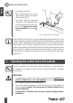
5. First installation ENGLISH ENGLISH INSTALLER INSTRUCTIONS Do not leave packaging material waste unguarded in the household environment. Separate the various packaging waste materials and deliver them to the closest selective waste collection centres. In order to remove all manufacturing residues, we recommend cleaning the appliance. For further information on cleaning see Chapter 15 6. [Page 37].
50 50 • The distance of the cooker hob from the back edge must be at least 50 mm; • The distance of the cooker hob from the walls that exceed worktop height must be at least 100 mm; • Make sure that there is a minimum distance of 750 mm from the burner to any shelf placed vertically above it; ENGLISH INSTALLER INSTRUCTIONS 100 Fig.
ENGLISH INSTALLER INSTRUCTIONS • Accurately clean milling. • Before positioning the top, lay the sealer gasket provided on the entire milling surface [Fig. 5]. • Once these operations have been completed, use the supplied brackets to fasten the hob to the structure. Refer to the “Fastening the cooker hob to the cabinet” paragraph [Page 26]. Fig. 5: positioning the insulating gasket A constant light of at least 0.
7.1 ENGLISH INSTALLER INSTRUCTIONS Fixed hooks They make it possible to fasten the cooker hob using fixing frames pre-set along specific points.
ENGLISH INSTALLER INSTRUCTIONS Set hook B in frame A welded to the hob, making sure that it is blocked in the specific holes based on top thickness (for a 30 mm thick top, lock the hook in the the highest hole in the frame; for a 40 mm thick top, block the hook in the lowest hole of the frame). A 30 B D Rotate tongue CA until it is positioned above the top, then tighten screw D. C A 40 B D 7.2 C Sliding hooks Make it possible to fasten the cooker hob without pre-set fastening points.
7.3 ENGLISH INSTALLER INSTRUCTIONS Fixed brackets Make it possible to fasten the cooker hob in pre-set fastening points. Standard edge (8 mm) B A Introduce the bracket B in appropriate top seat. Manually lock the bracket using screw A. 8. Connecting the cooker hob to the gas network It is necessary for the gas supply system to conform to local regulations in force.
ENGLISH INSTALLER INSTRUCTIONS IMPORTANT: Always place the gasket between the hob fitting and the connection pipe. • If using a stainless steel flexible pipe, it must be installed so that it does not come in contact with any part of the cabinet, but passes through an unoccupied area where its entire length can be inspected. Maximum extension of the flexible pipe must be less than 2 metres. • The gas fitting is the type with a 1/2” gas ISO R7 tapered thread.
INSTALLER INSTRUCTIONS ENGLISH 10. Discharging combustion products (exhaust) Discharge of combustion products must be ensured through hoods connected to an efficient natural draught flue, or through a forced exhaust. An efficient exhaust system requires an accurate design by a specialist that is approved for this work, following positions and distances contained in regulations. IMPORTANT: At the end of the intervention the installer must issue a conformity certificate. 11.
Gas type Burner Series No. II METHANE GAS G20 20 mbar ENGLISH INSTALLER INSTRUCTIONS III AE 2 3 4 5 10 6 7 8 9 11 12 13 14 Ref. Auxiliary Semi-quick Quick Triple crown Dual Auxiliary Semi-quick Quick Triple crown Auxiliary Semi-quick Quick Dual gear Rated capacity (KW) 1,00 1,75 2,70 3,50 4,50 1,10 1,75 3,00 3,80 1,00 1,75 3,00 5,00 Rated conInjector Min sumption rated capacity (l/h) (ø mm) (KW) 95 0,72 0,52 167 0,97 0,52 257 1,08 0,90 333 1,35 1,80 429 i 0.72 / and 1.02 i 0.46 / and 0.
IMPORTANT: After adjusting for use with a gas that is different from the initial testing one, replace the label on appliance housing with the one that corresponds to the new gas type. 12. Adjustment of the minimum Instructions for urban and methane gas 1. Light the burner and bring it to the minimum position. 2. Remove the gas tap knob and turn the adjustment screw [Fig. 8] inside or on the side of the tap rod (depending on the model), until a regular minimum flame is obtained. 3.
ENGLISH USER INSTRUCTIONS It is mandatory to have an earth connection as per modes foreseen in the electrical system safety standards. • If using a fixed connection, it is necessary to pre-set an omnipolar interruption device on the appliance power supply line with a contacts distance that is equal to or greater than 3 mm, located in a position that can be reached easily and is in proximity of the appliance. • If using a connection with a plug and socket, verify that they are of the same type.
The upper cover (B) of the burners must be placed in opposite seat with the two introductions notches in correspondence of the two cylinders below (C) and tighten clockwise. The associated burner is indicated near each knob. The appliance is equipped with an electric ignition device. It is sufficient to press the knob and rotate it anti-clockwise to the maximum flame symbol, until it is lit.
ENGLISH USER INSTRUCTIONS 14.2 Practical recommendations for burner use For better burner yield, and minimum gas consumption, it is necessary to use flat and regular bottom pots, equipped with a cover and proportioned to the burner, in order to avoid that the flame goes up their sides (see the “Pots diameter” paragraph [Page 36]). When boiling, reduce the flame as much as needed to make sure that the liquid does not overflow. Fig.
USER INSTRUCTIONS ENGLISH 15. Cleaning and maintenance Do not use a steam jet to clean the appliance. Before any intervention it is necessary to disengage the appliance power supply. Avoid leaving acid or alkaline (vinegar, lemon juice, salt, tomato juice,...) substances on the steel, grids and other parts of the appliance. 15.1 Cleaning the stainless steel In order to properly preserve the stainless steel, it is necessary to regularly clean it after each use, once it has cooled down. 15.1.
ITALIANO Riepilogo piani cottura a gas Legenda Serie II III ENGLISH AE Tipo di bordo N. 1 2 3 4 5 10 6 7 Bruciatore Manopola di comando Ausiliario Semirapido Rapido Tripla corona Dual Ausiliario Semirapido Potenza (W) 1.000 1.750 2.700 3.500 4.500 1.100 1.750 Bordo Q4 (4 mm) 8 9 11 12 13 14 Rapido Tripla corona Ausiliario Semirapido Rapido Doppia corona 3.000 3.800 1.100 1.750 3.000 5.
1.1 4000 N7272V N7272V 9 8 7 1.5 9 6 7 N7252V 7 521 +10 7 N7270V 7 7 R10.5 921 +10 900 +10 500 +10 1 6 10.5 A = 860 mm B = 480 mm 521 +10 9 1.5 N7270V 8 921 +10 900 +10 R10.5 1 6 10.5 A = 860 mm B = 480 mm 500 +10 8 1.5 N7252V 9 1221 +10 1200 +10 R10.5 521 +10 500 +10 1 A = 1160 mm B = 480 mm 10.
N7253V 8 7 521 +10 6 851 +10 830 +10 R10.5 1 8 7 N7251V N7251V 10.5 7 1.5 A = 560mm B = 480 mm 7 9 6 1 N7254V A = 1162 B = 351 mm 188 +1 0 600 +1 0 N7254V 1.5 N7254V A = 1159 mm B = 348 mm R10.5 +1 8 7 369 0 351 +10 6 521 +10 1 621 +1 0 R10.5 500 8 10.5 A = 830 mm B = 480 mm 500 +10 7 1.
14 N7278V-AEO A = 430 mm B = 480 mm 1 10 N7277V A = 430 mm B = 480 mm 1 12 N7276V-AEO A = 360 mm B = 480 mm 1 11 189
1.2 QUADRA N7214V 3 5 A = 1162 mm B = 351 mm 2 1 1180 +10 1162 +10 369 +10 R10.5 N7211V 1.5 N7211V 5 A = 862 mm B = 351 mm 2 1 926 +10 908 +10 369 +10 R10.5 351 +10 3 N7221V A = 309 mm B = 454 mm 190 454 +10 468 +10 R11 1 7 1.5 N7221V 3 9 351+10 4 1.
N7223V A = 309 mm B = 454 mm 1 323 +1 0 309 +1 0 454 +10 468 +10 R11 N7238V 7 1.5 N7223V 5 157.8 +10 955.5 +10 351 +10 45° 2 5 2 1 351 +10 955.5 +10 4 N7238V R10.5 +1 351 0 369 +1 0 1 45° R10.5 9 157.8 +1 0 1.5 R9.5 9 955.5 +1 0 973.
KE 7 9 7 N7600VKE N7603VKE 1.5 1.3 A = 840 mm B = 480 mm R10.5 1.
1.5 PROFESSIONALE N7055V-10 3 5 3 N7055V-10 4 A = 840 mm B = 480 mm 874 +10 +1 860 0 R10.5 514 +10 500 +10 1 2 N7053V-10 N7053V-10 1.5 3 A = 560 mm B = 480 mm 3 2 +1 0 +1 0 500 2 514 R10.5 1 5 7 1.
5 N7061V-08 A = 270 mm B = 480 mm 1 LISA 828.8 N7290V 506.8 5 587 8 7 303 R161 R1262.5 1.6 R93.5 200.5 6 R168 842.8 +10 828.8 +10 506.8 R1269.5 601 +10 587 +10 303 1 R161 R1262.5 N7290V R93.5 200.5 194 R100.5 1.
1.7 FAUST N7047VFT1 N7075V 5 3 N7048V 7 1.5 3 A = 770 mm B = 480 mm +1 804 0 +1 790 0 3 1.8 1 514 0 +1 500 0 +1 R10.5 2 ELEONORA N7095V N7295V 770 3 5 480 A = 770 mm B = 480 mm 3 R135 N7296VFT 1.
1.9 VULCANO N7297V 10 1.5 N7097V 10 3 7 A = 950 mm B = 480 mm +1 1 +1 0 500 514 +10 984 0 +1 970 0 R1 45 R152 1.
7 8 N7063V A = 420 mm B = 480 mm 6 1 N7367V 8 7 1.5 8 7 +1 +1 7 1 6 514 0 +1 500 0 774 0 760 +10 R1 45 R152 7 8 1.
1.11 ELETTRA - PANDORA 3 5 3 N7064V A = 560 mm B = 480 mm 4 1 3 2 5 3 N7065V A = 560 mm B = 480 mm 4 1 2 1.12 MAGIC N7044V N7024V 4 1.
3 N7021V A = 740 mm B = 480 mm 5 1 4 N7042V 3 3 7 1.5 N7023V A = 560 mm B = 480 mm +1 614 0 +1 600 0 +1 0 +1 0 2 500 4 514 1 R1 45 R152 1.
1.14 ANGOLARE N7038V 5 810 +4 0 619 1 3 20x45° 619 810 +4 0 480 2 +4 0 191x45° 3 3 480 +4 0 330 810 1.
1.16 RONDÒ - GIOTTO 4 N7052V Ø 500 mm 3 2 1 10 N7051VG Ø 500 mm 1 1.17 ALFA N7260V 5 8 1.5 N7260V 7 N7260V A = 840 mm B = 480 mm +1 874 +10 860 +10 7 1 6 514 0 +1 500 0 R10.