RBC20-60 Blast Chiller
Contents Page Introduction Model Details Controller Technical Detail Parts List Operating Instructions Electrical Connections Service Information Diagnostics Function Test Passcode Profiles Parameter Access Parameters Parameter Definitions Alarms and Warnings Foot Print Test Operation Probes Technical Data Wiring Diagrams 1 to 2 2 2 2 3 to 6 7 7 to 19 8 8 8 9 9 9 to 11 11 to 18 18 19 19 20 to 22 23 to Introduction. Cook Chill Operation.
The controller will determine the temperature to be maintained during the hold phase based on the chilling cycle that has been completed. If a soft or hard chill has taken place the controller will maintain an air temperature of 2°c. The hold mode is principally intended as a temporary storage facility offering the operator flexibility until the product can be unloaded into a longer term storage units at the correct storage temperature.
Blast Chill & Shock Freeze Operating Instructions. Standard Operation When mains electrical power is first applied to the controller it will carry out a self-test function, for approximately 3 seconds. During this period the display will show. On completion of the self test, the controller will revert to the last chill program that was run (Pre-chill, Soft Chill, Hard Chill, Hard Chill Max, Shock Freeze, Professional 1, Professional 2, or Professional 3).
Pre Chill This program is used to Pre Chill the cabinet prior to the first cycle. This is done with the Blast Chiller empty and is a short time based program of about 20 minutes. It is generally recognised as the correct method of preparing for a blast chill cycle. The program is selected by rotating the dial until the display shows, press and release the dial to start the program. Defrost.
Information Whilst in the program selection screen press and hold the dial for 2 seconds, the information screen will be displayed. Rotate the dial until ‘INFORMATION’ is highlighted. Press and release the dial to display the screen showing the last run cycle. The information relates to date, program run, start time, start temperature and end temperature. HACCP settings. Whilst in the program selection screen press and hold the dial for 2 seconds, the information screen will be displayed.
High Temperature: This alarm will only occur in the hold mode only. Probe the product to determine it is at the correct temperature. If it is at the correct temperature place in a storage refrigerator or freezer and call your Foster Authorised Service Company. If the product temperature is above the guidelines check the chill time selected or the weight of product being chilled does not exceed the specification for the Cabinet.
Electrical Connections. Inputs. L N E - Mains ‘Live’ supply (115V 230V, 50Hz / 60Hz). 4 terminals. Mains ‘Neutral’ supply – 16 terminals. Protective Earth – 16 terminals. DOOR DOOR2 HP - Door Switching connection (not voltage carrying). Safety door switch connection (not voltage carrying). High Pressure switch connection (not voltage carrying). TA TE FP1 FP2 FP3 - Air probe connection. Evaporator probe connection. Food/ product temperature connection.
Diagnostics Rotate the dial until you reach ‘Diagnostics’, below left, press and release the dial to highlight the component. In this program you can test each of the major components on the machine in sequence, 1- COMPRESSOR, 2-FAN1, 3-FAN2, 4- DEFROST, 5- ALARM, 6- CCAP (Capacity Control), 7- UV-L (UV light if fitted), ESC (escape). Rotate the dial until the relay output is highlighted, once selected press and the dial to test the relay, the relay will remain energised for as long as it is pressed.
Profiles. You are now in the program profiles. The controller has 9 operating programs – Pre Chill, Soft Chill, Hard Chill, Hard Chill Max, Shock Freeze, Professional 1, Professional 2, Professional 3, Defrost and 2 optional programs – UV Sanitisation and Information. These programs are all available depending upon which of the profiles are selected, see below. To change the profile rotate the dial to select program, press and release the dial to accept the change.
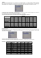
P14 P15 P16 P17 P18 P19 P20 P21 P22 P23 P24 P25 P26 P27 P28 P29 P30 P31 P32 P33 P34 P35 P36 P37 P38 P39 P40 P41 P42 P43 P44 P45 P46 P47 P48 P49 P50 P51 P52 P53 P54 P55 P56 P57 P58 P59 P60 P61 P62 P63 P64 P65 P66 P67 P68 P69 P70 P71 P72 P73 P74 P75 P76 P77 P78 P79 P80 P81 P82 P83 P84 P85 HARD MAX AIR TEMP Chill Time CHILL TEMP HOLD TEMP SHOCK FREEZE AIR TEMP CHILL TIME CHILL TEMP HOLD TEMP PROFFESSIONAL 1 Air Temp. Std. Chill Time Std. Chill Time Minimum Chill Time Maximum Chill Temp. Std. Chill Temp.
P86 P87 P88 P89 P90 P91 P92 P93 P94 Alarm Buzzer Air Probe Offset Coil Probe Offset Food 1 Offset Food 2 Enable Food 2 Offset Food 3 Enable Food 3 Offset Address Function °K °K °K Function °K Function °K Integer NO -15 -15 -15 NO -15 NO -15 1 YES 15 15 15 YES 15 YES 15 255 NO 0 0 0 NO 0 NO 0 255 Parameter Definitions Pre-Chill P01 Pre-Chill Enable The air temperature, which the air probe must read before the condensing system is de-energised in the chill mode of the Pre-Chill Program.
P13 Change Temp The percentage of a temperature based chill cycle, which is passed before automatically adjusting the air temperature set point to 1°C.The range is adjustable in 5% increments. Range 5% to 95%. Hard Max P14 Air Temp The temperature, which the air probe must read before the condensing system is de-energised in the chill mode of the Hard Chill Max Program. Range -20°C to 15°C.
P27 Chill Temp Minimum The minimum value that the temperature, which Food Probe 1 must read before the condensing system is deenergised in the chill mode of the Professional 1 program, prior to entering the Hold mode of a temperature based cycle, which it can be adjusted to by the operator. Range -20°C to -5°C.
P40 Chill Temp Maximum The maximum value that the temperature, which Food Probe 1 must read before the condensing system is deenergised in the chill mode of the Professional 2 program, prior to entering the Hold mode of a temperature based cycle, which it can be adjusted to by the operator. Range -5°C to -15°C. P41 Hold Temp Std The standard temperature, which the air probe must read before the condensing system is de-energised in the Hold mode of the Professional 2 Program. Range -15°C to 15°C.
P53 Hold Temp Std The standard temperature, which the air probe must read before the condensing system is de-energised in the Hold mode of the Professional 3 Program. Range -15°C to 15°C. P54 Hold Temp Minimum The minimum value that the Hold temperature set point can be adjusted to by the operator in the Professional 3 program. Range -10°C to 0°C. P55 Hold Temp Maximum The maximum value that the Hold temperature set point can be adjusted to by the operator in the Professional 3 program.
Note: The fan 1 hold operation does not effect routine defrost operation. P66 FAN 2 Hold Operation Determines the evaporator fan relay energisation during ‘Hold’ mode. ‘OFF’ = Evaporator fan 2 relay is not energised in ‘Hold’. ‘CYCLE’ = Evaporator fan 2 relay cycles with condensing system relay in ‘Hold’. ‘AUTO’ = Evaporator fan 2 relay cycles with condensing system and fan hysteresis in ‘Hold’. ‘ON’ = Evaporator fan 2 relay is always energised in ‘Hold’.
NO = No safety door switch fitted. YES = Safety door switch fitted. Note: Usually fitted to the evaporator fan door on Modular Blast Chillers. P79 Door Switch 1 Determines if a door switch is fitted or not, and consequently dictates Evaporator Fan operation, UV Sanitisation operation and door alarm activation’s. Also used to initiate the controller from the energy saving mode. NO = No door switch fitted. YES = Door switch fitted.
NO = No third food probe fitted. YES = Third food probe fitted. P93 Food 3 Offset Allows the value of Food Probe 3 to be offset allowing for the product temperature to be accurately measured. Range -15°C to +15°C. P94 Address The controller peripheral number. This is only necessary when controller are linked via a network to a computer management and data recording system (such as with the Foster TAB or ARGO systems). Range 00 to 255.
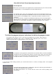
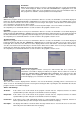
Foot Print Test operation The foot print test is a method of checking the operation of the process in a reduced time period The foot print test takes ten minutes. The first ten seconds are used for the display test, after that the relays are energised in a simple operating pattern to ensure each are energised. During the final ten seconds the alarm is sounded to indicate the end of the test. The graph below shows how the relays are energised relating to time.
Technical Data Nominal Chilling Capacity Duty @ -15°C Fans Evaporating Temperature HP Switch Setting Refrigerant Control Refrigerant Refrigerant Quantity System 1 System 2 Electrical Supply Total Heat Rejection RBC20-60 60Kg 3800w 3 -15°C RBC20-60R 60Kg 3800w 3 -15°C TEV R404a TEV R404a 1900grms 1900grms 400/3/50 – 16amp 1500w 230/1/50 13 amp (Fans & Defrost) Important Note There are two refrigeration systems on this model Refrigerant used is R404A.
SERVICE PLATE SYSTEM 1 & SYSTEM 2 PHIALS MUST BE FITTED IN THE HORIZONTAL POSITION AND CORK TAPED FAN PLATE EVAPORATOR ASSEMBLY RBC20-60 21
LP SW. PHIAL COMPRESSOR PHIAL LP SW. COMPRESSOR STAT CONDENSER - DUAL CIRCUIT EVAPORATOR – DUAL CIRCUIT HP SW. EXP. VALVE SIGHT GLASS SOL. VALVE DRIER LIQUID RECEIVER EQUALISING LINE HP SW. EXP. VALVE EQUALISING LINE SIGHT GLASS SOL.
COMPRESSOR WIRING RBC20-60 23
RBC20-60 1 of 2 Wiring Diagram 24
RBC20-60 2 of 2 Wiring Diagram 25
RBC20-60R 1 of 2 Wiring Diagram 26
RBC20-60R 2 of 2 Wiring Diagram 27
2
3
Foster European Operations France Foster Refrigerator France SA Tel: (33) 01 34 30 22 22 Fax: (33) 01 30 37 68 74 Email: info@fosterfrance.com Germany Foster Refrigerator Germany Tel: (0781) 96 93 00 Fax: (0781) 96 93 019 Email: info@fosterrefrigerator.de Foster Refrigerator Oldmedow Road, King’s Lynn, Norfolk Pe30 4JU England Tel: 01553 691122 Fax: 01553 691447 Website: www.fosterrifrigerator.co.uk Email: sales@foster-uk.com a Division of ITW (UK) Ltd.