OPERATION AND MAINTENANCE MANUAL RONDO’ gas cooker hobs cod. 7052 142, 7052 642 Foster spa - via M.S. Ottone, 18/20 - 42041 Brescello (RE) Italy - www.fosterspa.com tel. +39.0522.687425 - tel. Servizio Assistenza +39.0522.684450 fax +39.0522.686019 - fax Servizio Ricambi +39.0522.962166 e-mail: service@fosterspa.
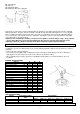
INSTALLATION INSTRUCTIONS TECHNICAL DATA MODELS Burners A 1 SR 1 R 1 TC - - Automatic ignition Safety valve Product dimensions (W x D) in mm Cut-out dimensions (W x D) in mm yes yes Ø 520 Ø 500 Installation The purchaser is responsible for installation: the Manufacturer does not offer this service. Any technical assistance activities carried out by the Manufacturer relating to faulty installation are not covered by the warranty.
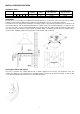
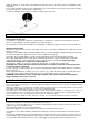
Applying the sealant Important - the picture below indicates how the sealant must be applied along the entire edge. This appliance is designed for non-professional use in domestic environments. Installation room The use of a gas cooker hob generates heat and humidity in the room in which it is installed. Make sure the room is well ventilated by keeping any natural ventilation openings open or by installing a cooker hood with flue duct (Fig. 1-2).
DECLARATION OF CONFORMITY. Regarding the components intended to come into contact with foodstuffs, this appliance conforms to the specifications of Italian Legislative Decree no. 108 dated 25/01/1992 which implements European Directive 89/109/EEC. CE - Appliance manufactured in conformity to European Directives 90/396/EEC, 89/336/EEC, 93/68/EEC, 73/23/EEC and subsequent amendments.
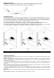
A1 =Gas rail pipe A2 =Gasket A3 =Adjustable fitting A4 =Rigid or flexible gas supply pipe Exclusively use pipes that conform to UNI-CIG 9891 specifications and sealing gaskets that conform to UNI-CIG 9264 specifications. The pipes must be installed so that when fully extended, their length does not exceed 2,000 mm. To facilitate installation and avoid the risk of gas leaks, it is advisable to first connect the adjustable fitting to the cooker hob then subsequently to the gas supply pipe.
Switch the burner on, set the valve to the minimum position then remove the knob (it is pressure-fitted thus easily removable). Use a small screwdriver to turn the valve adjustment screw - anti-clockwise to increase the gas flow and clockwise to reduce the gas flow - until the flame is 3-4 mm long. For LPG (in cylinder), turn the by-pass clockwise until it reaches the end.