Owner’s Manual Model AP1020/AP2090/AP2130 STEREO POWER AMPLIFIER
CAUTION RISK OF ELECTRIC SHOCK DO NOT OPEN CAUTION: TO REDUCE THE RISK OF ELECTRIC SHOCK, DO NOT REMOVE COVER (OR BACK). NO USER - SERVICEABLE PARTS INSIDE. CAUTION: TO PREVENT ELECTRIC SHOCK, MATCH WIDE BLADE OF PLUG TO WIDE SLOT, FULLY INSERT. ATTENTION: POUR EVITER LES CHOCS ELECTRIQUES, INTRODUIRE LA LAME LA PLUS LARGE DE LA FICHE DANS LA BORNE CORRESPONDANTE DE LA PRISE ET POUSSER JUSQU AU FOND.
INTRODUCTION Fostex new AP Series amplifiers AP1020, AP1020, AP2090 and AP2130 are designed to withstand severe operating conditions. It is a commercial use amplifier containing high technology citcuits designed for stability, durability, small size and large output. Contents Controls and connections (Model AP2090/AP2130)..................................2 Controls and Connections (Model AP1020)..............................................3 Outstanding features.............................................
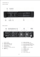
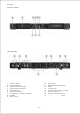
AP2090/AP2130 FRONT PANEL REAR PANEL 1. 2. 3. 4. 5. 6. 7. 8. 9. 10. 11. 12. 13. 14. Power switch Power indicator Output level controller Output level indicator Clip indicator Thermal indicator Compressor / limiter indicator Handle Filter cover 15. 16. 17. 18. 19. 20.
AP1020 FRONT PANEL REAR PANEL 1. 2. 3. 4. 5. 6. 7. 8. 9. Power switch Power indicator Output level controller Output level indicator Clip indicator Thermal indicator Compressor / limiter indicator Handle Filter cover 10. 11. 12. 13. 14. 15. 16. 17.
OUTSTANDING FEATURES 1) Forced cooling When the amplifier internal temperature rises, thee cooling fan automatically changes to high speed to force cool the heat sink for protecting the amplifier. 2) Level indicator (AP2090, AP2130) This LED is lit in 5dB steps over the 0 ~ - 30dB range to check the input signal. 3) Clip indicator This LED is lit at overload. It will flash on large instantaneous inputs but will not pose any problems.
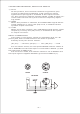
CROSSOVER NETWORK, SELECTOR SWITCH 1) FULL At this position, the crossover network is bypassed, (Hz) control pot becomes ineffective, a flat response output against the input signal is obtained at the output connector. The crossover network outputs (HIGH, LOW) at each connector will be those set by the crossover frequency adjustinig knobs. 2) HIGH When this position is selected, the HIGH PASS signal whose cutoff frequency is set by the (Hz) knob, is obtained at the speaker output connector.
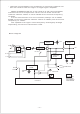
MULTI-AMPLIFIER SYSTEM EXAMPLE USUNG AP2090/2130 [Example of 2 way system] AMP 1 (HIGH PASS AMP) INPUT INPUT FULL HIGH H H.SP LOW L HIGH OUT LOW OUT AMP 2 (LOW PASS AMP) INPUT FULL HIGH H L.SP LOW L HIGH OUT LOW OUT [Example of 3 way system] AMP 1 (HIGH PASS AMP) FULL INPUT HIGH H H.SP LOW L HIGH OUT LOW OUT AMP 2 (BAND PASS AMP) INPUT FULL HIGH M.SP H LOW L HIGH OUT LOW OUT AMP 3 (LOW PASS AMP) FULL INPUT H L HIGH LOW HIGH OUT LOW OUT —6— L.
* General use amplifiers not containing a crossover network can also be used for the low region or high region amplifier. When Ap20909/2130 are to be used as a full range amplifier, harmful sub-sonic frequencies can be cut off if the crossover network selector switch is set to HIGH and crossover frequency to 30Hz. If a line transformer is to be connected, always set to HIGH PASS (crossover network selector switch to HIGH) and crossover frequency to 100Hz.
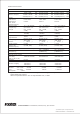
SPECIFICATIONS AP1020 AP2090 75W+75W. . . . 8Ω 100W+100W. . . 8Ω 200W(mono). . . 8Ω 300W+300W. . . 8Ω 450W+450W. . . 4Ω 900W(mono). . . 8Ω AP2130 [AMPLIFIER SECTION] Rated output Total harmonic distortion (At 1kHz rated output) Reproduce frequnecy range S/N ratio Input impedance Damping factor Less than 0.05% Less than 0.05% Less than 0.