
Owner`s manual


E-4
Names and functions
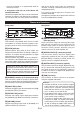
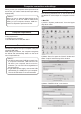
Rear panel
❼
[ANALOG OUTPUT] (L and R) connectors
(RCA pin jacks)
These connectors output an analog audio signal
after the D/A converter They are active when the
[OUTPUT SEL] switch on the front panel is set to
the down (“RCA”) position. Generally, They are
used to connect to an audio amplier, etc.
❽
[DIGITAL OUTPUT] connector (optical)
This connector directly outputs a digital audio
signal being received by the unit (via the [USB] or
[DIGITAL INPUT] connector) in S/PDIF format. It is
used to connect to a digital audio device.
❾
[DIGITAL INPUT] connector (optical)
This connector receives an S/PDIF digital audio sig-
nal. It is active when the [INPUT SEL] switch on the
front panel is set to the up (“OPTICAL”) position. It
is used to connect to a digital audio playback de-
vice such as a CD player.
❿
[USB] connector
This connector is used to connect to a computer
using the supplied USB cable.
<Memo>
• Via USB, the HP-A3 not only receives a digital
audio signal but also gets power (USB bus
power) from a computer. Therefore, always
make USB connection to your computer and
turn it on when you use the HP-A3.
• To get stable power supply, connect the USB
cable directly to a USB port of your com-
puter, without using a USB hub.
• To receive a digital audio signal from your
computer via USB, you should make audio
output setting of the computer appropriately,
as well as setting the [INPUT SEL] switch of
the HP-A3 to the down (“USB”) position.
Front panel
❶
[POWER] indicator
This indicator is illuminated when the unit is USB-
connected to a computer and the computer is sup-
plying the power to the unit via the [USB] connector.
❷
[LOCK] indicator
While the [INPUT SEL] switch is set to “USB”, this
indicator is illuminated when the HP-A3 is USB-con-
nected to a computer and recognized as an digital
audio device by the computer.
While the [INPUT SEL] switch is set to “OPTICAL”,
this indicator is illuminated when the HP-A3 is re-
ceiving the S/PDIF signal from a digital audio device
that is connected to the [DIGITAL INPUT] connector.
<Note>:Even though the [LOCK] indicator is il-
luminated while the [INPUT SEL] switch is set to
“USB”, if the audio output device of the com-
puter is set to any device other than the HP-A3,
the HP-A3 does not receive an audio signal.
❸
[PHONES] connector (1/4” stereo phone jack)
This connector is used to connect to stereo head-
phones. It is active when the [OUTPUT SEL] switch on
the front panel is set to the up (“PHONES”) position.
❹
[INPUT SEL] switch
Switches the digital input source between the [USB]
and [DIGITAL INPUT] connectors.
❺
[OUTPUT SEL] switch
Switches the analog output destination between
the [PHONES] and [ANALOG OUTPUT] connectors.
❻
[VOLUME] control
Adjusts the analog output level of [PHONES] and
[ANALOG OUTPUT] connectors.
and (2) this device must accept any interference
received, including interference that many cause
undesired operation.
This Class B digital apparatus complies with
Canadian ICES-003.
Cet appareil numérique de la classe B est conforme
à la norme NMB-003 du Canada.
4. Compliance with Part 15 of FCC Rules and
Canadian ICES-003.
This device complies with Part 15 of the FCC Rules.
Operation is subject to the following two conditions:
(1) This device may not cause harmful interference,
- Consult the dealer or an experienced radio/TV
technician for help.