
DVD Location Recorder

43
Location Recorder Model PD204
Chapter 3: Names and Functions
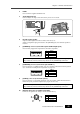
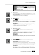
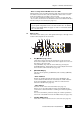
4. [TIME CODE OUT] connector (XLR-3-32 type/balanced)
Outputs time code.
5. [TIME CODE IN] connector (XLR-3-31 type/balanced)
Inputs external time code.
1
2
3
GND
HOT
COLD
1
2
3
GND
HOT
COLD
1
3
2
2
3
1
1
2
3
4
5
6
7
8
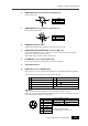
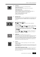
(*) V BATT (12V), Max 500mA.
It is output regardless of power on/off.
1
2
3
PLAY
STOP
REC
4
GND
5
6
7
SHIFT
REW
DC-OUT
8
FF
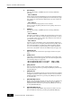
<Operation>
When each terminal is grounded, the corresponding function is active.
Note that you can always control the PD204 via this connector regardless of the set-
ting of the [PANEL LOCK] key on the panel.
SHIFT + STOP
SHIFT + REC
CUE
PAUSE
SHIFT + REW FILE
SHIFT + FF
FILE
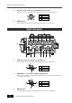
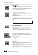
6. [WORD IN] termination switch
Terminates the word input signal by setting the switch to "ON".
7. [WORD/VIDEO IN] and [WORD OUT] connectors (BNC type)
The [WORD/VIDEO IN] connector receives word or video clock. It automatically
detects the clock type (word or video).
The [WORD OUT] connector feeds a word clock.
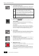
9. Angle adjustment arm
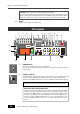
10. [PARALLEL] connector (MINI DIN 8-pin)
This connector accepts parallel remote signals for controlling the PD204 externally.
You can control the following nine operations remotely.
1
2
3
4
5
6
7
8
9
PLAY
STOP
RECORD
REWIND
F. FORWARD
CUE point registration
PAUSE
FILE
FILE
8. [9P-REMOTE] connector (D-sub 9-pin/female)
Not currently supported. Prepared for the future expansion.