8588 044 000 (396678) Digital Multitracker INPUT 1/9/A 2/10/B 4/12/D 3/11/C 5/13/E 6/14/F BAL 7/15/G UNBAL INSERT TRIM LINE MIC LINE MIC LINE MIC PEAK PEAK PEAK 1/9/A 2/10/B 3/11/C CH STATUS CH STATUS/CH SEL LINE MIC ORANGE MON OUT LINE PEAK MIC PEAK 4/12/D RED INPUT LINE MIC LINE PEAK 5/13/E 6/14/F REC GREEN MIC LINE PEAK 0 L INSERT PHONES R PHONES 0 10 10 PEAK 7/15/G PLAY MIC MON OUT 8/16/H UNBAL BAL 8/16/H OFF MUTE SCENE RECALL STORE CLEAR
CAUTION: CAUTION TO PREVENT ELECTRIC SHOCK, MATCH WIDE BLADE OF PLUG TO WIDE SLOT, FULLY INSERT. RISK OF ELECTRIC SHOCK DO NOT OPEN ATTENTION: POUR EVITER LES CHOCS ELECTRIQUES, INTRODUIRE LA LAME LA PLUS LARGE DE LA FICHE DANS LA BORNE CORRESPONDANTE DE LA PRISE ET POUSSER JUSQU' AU FOND. CAUTION: TO REDUCE THE RISK OF ELECTRIC SHOCK, DO NOT REMOVE COVER (OR BACK). NO USER - SERVICEABLE PARTS INSIDE. REFER SERVICING TO QUALIFIED SERVICE PERSONNEL.
Precautions About power supply • Be sure to connect the VF160EX to the power supply specified in the Specifications section of this owner’s manual. Do not use an AC outlet of any other voltage. • Before you change the location of the VF160EX, pack the unit in the shipping carton or an impact-resistant case. Make sure that the VF160EX is kept free from external vibration or impact since the VF160EX is very sensitive to vibration.
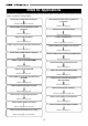
Index for Applications This index is provided for searching the page of the desired application. Please use this together with the “Table of Contents” which follow. I want to try recording a musical instrument. I want to listen any number of times to playback of a recorded tune. Please read pages 31 and 43. Please read page 69. I want to partially rerecord a previously recorded performance. I want to locate to the desired point. Please read page 37. Please read page 34. I want to format the hard disc.
I want to change the speed at playback/record. I want to locate to a point previous to the desired point. Please read page 68. Please read page 137. I want to manage the programs by naming them. I want to operate the faders in pairs. Please read page 71. Please read page 146. I want to operate the “Chain play mode”. I want to make a tempo map. Please read page 95. Please read pages 133 and 135. I want to operate the “audio CD playback mode”. I want to mixdown without using external equipment.
Table of Contents Safety Instruction .......................................................2 Precautions ..............................................................3 Index for Applications ...............................................4 •Auto Punch In/Out .............................................................38 Programming the PUNCH IN/OUT points ........................................38 Auto Punch In/Out take .......................................................................
Audio CD playback mode .................................................................103 Chapter 4 Recorder Functions • Switching the playback mode ................................................100 • Available functions in the audio CD playback mode .........104 Cueing/Digital Scrubbing ...............................................67 • Cueing with the [F FWD]/[REWIND] key ..........................67 • Shuttle Cueing ....................................................................
Chapter 1 Basic Features of VF160EX Introduction Congratulations! You have chosen a truly unique multitracking device. The VF160EX Fostex Digital Multitracker features a myriad of high-tech functions. These include a digital mixer incorporates high-performance DSP multi-effect made possible using the Fostex-original A.S.P. (Fostex Advanced Signal Processing) technology, as well as an integrated 16-track (+8 additional tracks) digital recorder that can record or play uncompressed 44.
Before Operating This section defines the contents, names and terms the user should know prior to actually operating the VF160EX. Please read the overview before going any farther with your new recorder as it will save you a lot of time in the long run. Two RECORDING Modes The VF160EX has 2 recording modes, called REC ASSIGN. DIRECT Recording BUSS Recording The first recording mode is the DIRECT REC mode. This recording mode is mainly used to: The second recording mode is the BUSS REC mode.
The following figure shows that track 1 is armed (READY), so that input A signal can be recorded on track 1. Regardless of whether executing DIRECT or BUSS recording, you must select recording sources and recording tracks. You can select them using the following keys, depending on the recording mode (DIRECT or BUSS) you are using.
In the following example, channel 16 which accepts input H is selected as a source channel. RECORDING System Unlike conventional systems, the VF160EX records on a hard disk storage device, instead of cassette tape. Sound source recording can start from any point on a formatted disk, as long as the point is within a 24 hour time range in ABS time. Note that it is also possible to move (locate) to any point within that time range, as well.
A mono-track refers to one track. Therefore, a mono-track REMAIN time is the recordable length on the hard disk space available when recording only one track. It is possible to compute the recordable time by dividing the REMAIN time with the number of tracks to record. Therefore, if four tracks are simultaneously recorded, then the recordable time is 46 minutes (3 hours 7 minutes divided by 4).
CH STATUS CH STATUS/CH SEL ORANGE RED INPUT REC GREEN PLAY OFF MUTE SCENE RECALL STORE CLEAR A Silence DIRECT RCL MAP EFF EDIT EFF1 [CH STATUS/CH SEL] key +6 +6 B Rec B Silence 0 0 C Rec B Rec C D Rec B Rec C Silence Silence Channels 1 to 8 Channel Fader Silence MUTE MUTE EFF1/EFF2 EQ/COMP HI-G/F/Q PRE/POST COMP AUX1/AUX2 MID-G/F/Q -10 -10 Rec D EFF2 -20 -20 -30 -30 -40 -50 -60 -40 -50 -60 -∞ -∞ PRE/POST PAN LO-G FADER CH VIEW CH PARAM EDIT 2 1 E
MTC set the ABS 0 location to MTC ** H** M**S. In other words, MTC sets the time base to start MTC from a certain time, which serves as the offset time, to synchronize the following 24 hour MTC time base with the ABS to count the time. If, for example, ABS 0 is set to MTC 1H, then MTC starts from 1H and ABS 1H (one hour elapsed) will be MTC 2H. * When pressing the [BUSS-SOURCE] key, the status will require selection of a channel to send to “REC BUSS”, as mentioned earlier.
Names and Functions WARNING: CAUTION TO REDUCE THE RISK OF FIRE OR ELECTRIC SHOCK, DO NOT EXPOSE THIS EQUIPMENT TO RAIN OR MOISTURE.
Top Panel Analog Input/Output Section 1 3 2 4 5 6 INPUT 1/9/A 2/10/B 4/12/D 3/11/C 5/13/E 6/14/F BAL 7/15/G UNBAL INSERT BAL TRIM LINE MIC LINE MIC LINE MIC PEAK PEAK PEAK 1/9/A 2/10/B 3/11/C LINE MIC PEAK 4/12/D MON OUT LINE MIC LINE PEAK 5/13/E MIC LINE PEAK 6/14/F MIC LINE PEAK 7/15/G 7 MIC 0 10 MON OUT 8/16/H UNBAL INSERT L PHONES R PHONES 0 10 PEAK 8/16/H 8 9 10 1. [INPUT] (Unbalanced) Jack: A to F 5.
Top Panel Mixer Section 11 CH STATUS CH STATUS/CH SEL ORANGE RED INPUT REC GREEN PLAY OFF MUTE SCENE RECALL STORE CLEAR MAP DIRECT RCL EFF EDIT EFF1 12 +6 +6 0 0 -10 -10 -20 -20 -30 -30 -40 -50 -60 -40 -50 -60 -∞ -∞ EFF2 MUTE MUTE EFF1/EFF2 EQ/COMP HI-G/F/Q PRE/POST COMP AUX1/AUX2 MID-G/F/Q PRE/POST PAN LO-G FADER 13 14 15 16 17 18 19 20 21 22 CH VIEW CH PARAM EDIT 1 2 CH STATUS CH STATUS/CH SEL 4 3 ORANGE 6 5 RED INPUT REC 7 GREEN PLAY 8 OFF TRACK
* Use the [CH STATUS/CH SEL] key to select the channel to change any settings together. 15. [EFF EDIT-EFF1/MUTE] Key * This is used to CHECK/CHANGE the EFFECT type and parameter settings of EFFECT 1. * Press this key while the [SHIFT] key is depressed to turn ON/OFF the mute feature of EFFECT 1. 23. [MASTER CH STATUS/CH SEL] Key * This becomes the master channel ON/OFF key when the LCD is in the normal display mode (described later).
Top Panel Recorder Section 25 26 27 28 34 33 32 35 43 INPUT SEL SOURCE REC ASSIGN BUSS REC TRK 29 30 31 DIRECT REC TRK DISP SEL PGM SEL SETUP TIME BASE CLIPBOARD ALIGN SEL OUT A RTN A PLAY INT MIXDOWN AUTO RTN AUTO PUNCH IN OUT START 1 5 4 3 2 IN END 7 6 MARK HOLD/ 40 41 42 47 48 49 52 54 53 55 RECORD AUTO PUNCH STORE EDIT SCENE SEQ. UNDO /REDO STOP PLAY CLIPBOARD PLAY LOCATE ABS 0 LOCATE REC END VARI PITCH LOCATE SCRUB P.
32. [AUTO RTN-START/MARK1] Key * This key is used to CHECK/CHANGE the parameters saved at the start point (AUTO RETURN START POINT) when executing auto return or auto repeat. * Press this key while the [SHIFT] key is depressed to CHECK/CHANGE the parameters saved in [MARK1]. * This can be used as Locate Memory. AUTO PLAY AUTO RETURN OFF AUTO REPEAT * Press this key while the [SHIFT] key is depressed to turn ON/OFF the scene sequence.
46. [SCRUB/CD PLAY] Key 51. [F FWD/NEXT] Key * This is used to digitally scrub sounds in the FWD and REV direction without any change in pitch. * Pressing this key while holding down the [SHIFT] key switches the playback mode between HDD playback and audio CD playback. * Press this key while the machine is stopped for 30X rewind speed. * 3X cuing (rewinding with sound) takes place when this key is pressed during the PLAY status.
* MIDI control signals such as MMC (MIDI Machine Control) is mainly input. * Connector: DIN 5 PIN Top Panel Display Section 59 64. [MIDI OUT] Jack 57 * Connect to the MIDI IN jack of an external MIDI device. * MIDI synchronization signals such as MTC (MIDI Time Code) and MIDI clock signals & song position pointers are mainly output. * Connector: DIN 5 PIN 60 ACCESS PHANTOM 58 65. [DIGITAL/DATA IN] Jack 57.
About the hard disk storage device The VF160EX is complete with a 3.5-inch E-IDE hard disk (storage device) which is formatted in the Master 16 mode. Therefore, there is no need to newly assemble a hard disk or to format the hard disk. The user can immediately start recording with the VF160EX. Note that the current hard disk can also be replaced with another model for use with the VF160EX. (However, please only use hard disks that Fostex recommends.
5. Press the [ENTER/YES] key while the [RECORD] key is depressed. If the “Standard” format is selected and executed, the formatting process takes place while showing the progress of the good sectors (Good ***MB) on the disk, bad sectors on the disk (Bad ***MB) and remainder (Remain ***MB). Nothing can be done during the formatting process. Please wait for a while until the process is completed. 6. Press the [EXIT/NO] key (or [STOP] key) to escape from the SETUP mode.
1. Unscrew the four screws fixing the panel to the bottom of the VF160EX main unit. 4. Prepare a new hard disk and connect the two cable connectors to it with holding the connector section. If the panel is removed, the hard disk covered with a cushion can be seen. Bottom 3 Connector 4 2 1 Hard disk unit Panel Connector Cushion 2. Take out the hard disk to the direction “2” indicated in the drawing below. 5. Put back the new hard disk into the VF160EX main unit.
Formatting the new hard disk Carefully follow the instructions below to newly format the hard disk properly. 1. Turn ON the VF160EX after plugging the power cable in the electric outlet. The VF160EX will startup. “Unformat!” will appear on the LCD. The menu will automatically go to the SETUP mode. The display showing the “Disk Format” menu appears. 2. Press the [ENTER/YES] key. The menu to select the format type appears. “****” represents the name of the drive.
Chapter 2 Basic Recording and Playback This chapter describes basic recording and playback with the VF160EX. Before carrying out recording/playback, read “About a demonstration song!”, “Connections of Peripheral Equipment” and “LCD”. About a demonstration song! (Read this before using the unit) Your VF160EX may have a demonstration song on program 1 (P01) when shipped (note that some VF160EX units may not have a demonstration song, depending on the production).
Connections of Peripheral Equipment The VF160EX is equipped with input/output jacks to connect the following sound sources and external equipment. Always turn the [MASTER] fader, [MON OUT] knob and [PHONES] knob to “0” when connecting the external equipment to the input/output jacks.
LCD The following describes the contents shown on the LCD and their operations. Menu shown when turning power ON Switching the Time Base When the VF160EX is turned ON with a hard disk already formatted, the following menu will appear in order: [Initial... (Initializing)] & [Version] -> [Current Dr] -> [IDE] -> [Name of Hard disk (Instantly)] -> [Recording mode (Standard or Quick)]. The head of the program (ABS 0) will then start up at the time base when the power was turned OFF.
Switching with [DISP SEL] Key *1. Every time the [DISP SEL] key is pressed the LCD alternately shows the “1. Normal Display of Current Time Base” -> “2. REMAIN Display of Current Time Base” -> “3. MTC Time Display Input”. The description of each display is defined below. The REMAINING time display appears as follows according to the time base that has been selected. 1. Normal Display of Current Time Base * Current time according to current time base. * Program number and program title.
Instructions for DIRECT Record This section describes the basic REC/PLAY procedures in the “DIRECT” recording mode, which is the easiest recording procedure and also provides recordings that most closely resemble the original. Hints and tips to successfully operate the VF160EX are included according to the work flow, ranging from the actual recording to mix down process. Both experienced and novice users of multitracker should try this process so as to learn the VF160EX operations.
Preparing to Record 1 Connect the sound source to record to the [INPUT] 1/9/ A jack. 2 Press the [INPUT SEL] key (Key: Flashes ORANGE). Tips: Level meter When carrying out step 8 mentioned above, levels for channel 1 and masters L and R are shown in the meters on the Normal display. [CH STATUS/CH SEL] key of ch9-16 -> Flashes GREEN Indicates that all channels are “TRK (Track)” (the following LCD display appears).
RECORDING to 2 Tracks With track 1 now recorded, we will record the stereo sound source to tracks 15 and 16 of the recorder.
PLAY Tips: Changing the recording mode To change the DIRECT recording mode to the BUSS recording mode, press the [BUSS-REC TRK] key while the tracks to be directly recorded are selected using the step above. "Rec Mode Change!" appears and "Sure?" flashes on the screen. 1. Locate the time to playback. 2. Press the [PLAY] key to start playback. Ch1, ch15 and ch16 faders can be used to adjust the play level of each track. After recording, put the “READY” track in the “SAFE” mode, as described earlier.
The following details are saved in each Memory Key. AUTO RTN AUTO PUNCH IN OUT START 1 2 3 IN END 5 4 CLIPBOARD ALIGN SEL 6 OUT 7 MARK Normally, the [CLIPBOARD-ALIGN SEL/MARK6] key can store the MARK6 memory. When doing a copy/paste (or move/paste) function, the time data stored in the [CLIPBOARD IN] key is automatically copied and stored in this key, allowing you to use it as the ALIGN SEL point. See “Copy/paste and Move/paste” on page 73 for details.
Locating an event memory You can store up to 99 event memory points (00 to 99). These event memory points can be used for locate functions described below as well as for the “scene event map” function described in “Chapter 3 Mixer functions”. Creating an event memory 3. After viewing the screen, press the [EXIT/NO] key. The display returns to the Normal display. Event memory numbers are assigned in ascending order of ABS time, regardless of order in which event memories are created.
Punch In/Out Punch IN/OUT recording enables you to record over previously recorded parts. This function comes in handy in the following cases. * If a recording is unsatisfactory in either recording or performance and you want to redo it. * If you want to record a solo part to another track while listening to the backup tracks. PUNCH IN refers to the process to switching from PLAY to REC. On the other hand, PUNCH OUT refers to the reverse process, to switch from REC to PLAY.
Auto Punch IN/OUT • AUTO PUNCH IN/OUT take Before carrying out an auto punch in/out operation, you must register the “PUNCH IN” and “PUNCH OUT” points. 1. After rehearsal is completed, locate the point immediately before starting the recording, as with step 2 of AUTO PUNCH IN/OUT rehearsal. Punch Out point Punch In point 3. Press the [RECORD] key while the [PLAY] key is depressed to start recording [TAKE]. Recording Track Playback Record “RHSL” changes to “TAKE”.
Track Exchange Up to now, we changed the input channel according to the track to record. However, there is also a way to record all tracks with one input jack. You can do this by exchanging a recorded track that was recorded normally with an unrecorded track. This procedure is called “Track Exchange”. This feature is convenient to use when recording with all G and H [INPUT] jacks that can be connected with a condenser mic or balanced output, for example.
Mixing After recording with DIRECT Recording, adjust the play level, equalize the sound or add some effects to the audio sound of track 1-16. This section describes how to adjust the level, PAN, equalizer, effect send level and effect. Level Adjustment Equalizer Adjustment • Use the Channel Fader to adjust the play level of each channel. Tips: For fader-paired channels (set by the “Pair fader setting” menu in the Setup mode), controlling EQ settings for one channel affects both channels simultaneously.
4. To adjust other channels, press the [CH STATUS/CH SEL] key of that channel. 5. When adjustments are completed, press the [EXIT/NO] key. The system returns to the Normal Display. Modifying Effect Type 1-1. Press the [EFF EDIT-EFF1] key. EQ curve The effect 1 selection menu appears along with the currently set effect type. 5. To adjust other items or another frequency range of the equalizer, press again the [HI-G/F/Q] key, [MID-G/F/Q] key or [LO-G] key. Then turn the [JOG] dial to modify the parameter.
Mix Down Create the master tape after adjusting all tracks. Start recording the piece with a master recorder (cassette tape, DAT, MD, etc.). The VF160EX can output S/P DIF (optical) digital signals making it is possible to directly mix down digital signals if the master recorder can input S/P DIF (optical) digital signals. Tips: Internal Mixdown Mode The VF160EX features an “Internal mixdown mode”.
Instructions for recording with BUSS RECORD This section will discuss the basic procedures to REC/PLAY with "BUSS" RECORD, which is another recording option. With DIRECT RECORD, the track recorded was determined according to the input of channel A to H. However, with BUSS RECORD, recording is possible regardless of the channel input. It is also possible to record the input of all 8 channels on 2 tracks with BUSS RECORD.
Recording the H Input Signal to Track 1 Here we will record a sound source connected to input H on track 1 of the recorder. Beforehand, set the ch1 to 16 channel faders, master fader and the [TRIM] for A to H to 0. Connect a headphone or speaker to monitor the sound.
It is possible to apply effect to the input signals by setting EFF1 or EFF2 to the source at the same time. Details are described later. Adjusting the Source Channel 9 Sound for monitoring purposes can be heard from the headphones or speakers from this point. Adjust the volume of the monitor sound with the [MON OUT] or [PHONES] knob. The channel signal sent to REC BUSS (ch16 in this case) are not directly output from the stereo OUT L/R channels.
Recording Play 1. Locate the time to start recording on the VF160EX. 1. Locate the time in which recording was started (REC start time). 2. Press the [PLAY] key while the [RECORD] key is depressed to start recording. 2. Press the [PLAY] key to check the sound recorded. The [CH STATUS/CH SEL] key and [RECORD] key of ch1 lights up RED, indicating that recording is taking place. The ch1 fader can be used to adjust the play level. The signals recorded on track 1 can be checked. 3.
Preparing to Record 1 Connect to the [INPUT] jack the sound source to record. 2 Press the [INPUT SEL] key. 3 Press the [CH STATUS/CH SEL] key of ch9-16 to switch ch 9-16 to "INPUT". Adjusting the Source Channel Press the [RECORD] key and set tracks 7 and 8 to the input monitor (RED: Flashing). 9 As in the earlier case, the monitor sound is output at this stage. Adjust the volume of the monitor sound with the [MON OUT] or [PHONES] knob. 10 Ch9-16 is ready to start signals of input A to H.
Tips: Applying an Effect on the Source Channel It is possible to apply effect sound on the source channel during BUSS RECORD. 1. EFF1 or EFF2 can also be selected at the same time for the source channel from the display (appears by pressing the [BUSS SOURCE] key) to select the source channel, as described earlier. The following figure shows the example where input H and EFF1 are both applied to the source channel, and allows EFFECT 1 to be applied to the input H signals. 2.
Chapter 3 Advanced mixer operations This section describes practical operations of the mixer including functions that are not described in "Basic operations" as well as detailed information about settings. Initial condition when the power is turned on When you turn the power on, the VF160EX shows the start-up display ("FOSTEX" -> "Initial.." -> "Current DR", "IDE" -> "Format Type" ["Standard" or "Quick"]), and then becomes ready.
Channel Parameter Edit You can edit the various parameter settings such as pan and equalizers for channels 1 through 16 and the master channel. We refer this type of editing as "Channel parameter edit". There are several channel parameter edit keys on the top panel (as shown below) and pressing the dedicated key for the parameter you want to edit brings up the corresponding edit screen.
3. Use the [HI-G/F/H] (or [MID-G/F/Q] or [LO-G]) or [HOLD/>] key to select a parameter. Adjusting EQ Each time you press the key, the flashing parameter (to be edited) changes in the following order. G -> F -> Q -> ON -> G ....(When setting the LO equalizer, the flashing parameter changes between G and ON.) The VF160EX provides a 3-band equalizer section including HI, MID and LO bands. You can control G (gain), F (frequency) and Q for HI and MID equalizers, while only G (gain) for LO. 4.
Controlling Effect send level Selecting pre/post of Effect sends You can control send levels of channels 1 through 16 (pre- or post-fader) to the two internal A.S.P. effect processors. The master channel controls the effect send master level. You can select whether the pre-fader or post-fader signal is sent from each channel (1 to 16) to the effect processor. If you select "Post", the signal adjusted by the channel fader is sent to the effect processor is also lowered.
5. After completing the pre/post selection, press the [EXIT/ NO] key. Selecting pre/post of AUX sends The VF160EX exits the channel edit mode and the display returns to the Normal display. You can select whether the pre-fader or post-fader signal is fed from each channel (1 to 16) to the [AUX SEND] jack. If you select "Post", the signal adjusted by the channel fader is sent to the effect processor, so if you lower the channel fader, the signal sent to the effect processor is also lowered.
5. After completing the pre/post selection, press the [EXIT/ NO] key. You cannot apply the equalizer to the input channels that the compressor is applied to. However, you can apply both the equalizer and compressor to the master channel. The VF160EX exits the channel edit mode and the display returns to the Normal display. Controlling fader levels The following operations are assumed that the compressor is applied to channels 13 and 14.
4. After completing the parameter setting, press the [EXIT/NO] key. If two adjacent channels are fader-paired, when pressing the [CH STATUS/CH SEL] key for the even channel, the fader icon in the figure shown in step 3 above is shown in dotted line. See page 146 for details about how to pair faders of adjacent two channels. The VF160EX exits the channel edit mode and the display returns to the Normal display.
Effect Edit Mode The VF160EX offers high quality ambient effects by employing the A. S. P. (Fostex Advanced Signal Processing Technology), which is exclusively developed by Fostex. With the A. S. P., you can obtain an incomparably clean and high density Hall Reverb, overwhelmingly clear Room Reverb and wonderfully hi-fidelity Plate Reverb.
About the effect types The VF160EX contains two independent DSP multi-effect units; EFF 1 and EFF 2. A variety of effect types are preset for each effect unit. By selecting a suitable effect type, you can process the sound as you wish. You can also edit the parameters of the selected effect type to create your own effect sounds. The following 28 effect types are preset for EFF 1. The 38 effect types shown on the next page are provided for EFF 2, and these include the same 28 effect types as EFF 1.
Effect types preset for EFF 2 Name L01 ~ L28 Parameter type Explanation 1~28 are the same effect types as the EFF 1 presets listed on the preceding page. (For details refer to the preceding page.) L29 MonoDELAY DELAY Mono delay L30 PanDELAY DELAY Panning delay L31 MonoBpmDL BPM DELAY Mono delay. Specify BPM and note value to set the delay time. L32 PanBpmDL BPM DELAY Panning delay. Specify BPM and note value to set the delay time.
3. Use the [JOG] dial to adjust the value. < Note > For details on the meaning and range of each parameter, refer to "Effect parameter details" on the below. When you press the [ENTER/YES] key to finalize the effect type, the sound will be muted for an instant. 4. If you wish to adjust another parameter, repeat from . Effect parameter settings Here's how to set the effect parameters. 5. When you are finished making settings, press the [EXIT/NO] key twice to exit Effect Edit mode. 1.
BPM delay effect parameters (parameter type: BPM DELAY) For effect types 31 and 32 of the preceding "Effect type" table, the following four parameters can be adjusted. 1. Eff Level 2. BPM 3. Note 4. Feedback 5. Filter Adjust the effect return level: 0~99 Adjust the BPM. Range: 30--250 bpm * If the delay time exceeds 680ms, “!” is shown. Select the note value for the delay. Range: 24, 16, 8T, 16...8, 4T, 8., 4, 2T, 4., 2, 2., 1 * 24 = 16th note sextuplets, 16 = 16th notes, 8T = 8th note triplets, 16.
Flanger effect parameters (parameter type: FLANGE) For effect type 36 of the preceding "Effect type" table, the following four parameters can be adjusted. 1. Eff Level 2. Rate 3. Depth 4. Mod Delay 5. Feedback Adjust Adjust Adjust Adjust Adjust the the the the the effect return level: 0~99 speed of modulation. Range: 0.01--2.00 Hz depth of modulation. Range: 0--99 modulation delay. Range: 0--200 number of modulation repeats.
Level adjust Scene memories stored in the scene numbers (00 to 99) are preserved even if the power is turned off. However, a temporary memory stored in the Temporary numbers disappear and all the parameters return to the default "Un-defined" settings when the power is turned off, though they do not disappear when changing the program.
Direct recall of a scene memory Besides recalling a scene memory by selecting the desired scene from the list as described above, you can recall a scene directly. If two adjacent channels are fader-paired, pressing the [CH STATUS/CH SEL] key for the odd channel selects both channels and you can simultaneously control both channels. The fader icon for the even channel as shown in a dotted line, indicating that you do not have to adjust it.
Scene Event Map By creating a scene event map, you can recall desired scene memories (mixer settings) at desired positions during playback. For example, you can recall scene memory 02 at 00H 01M 34S 00F and scene memory 04 at 00H 02M 20S 20F, etc. In the following description, we assume that the time base is set to ABS. However, you may set the time base to Bar/Beat/Clk which allows you to specify the event position by Bar/Beat/Clk numbers.
2. Select the desired event memory using the [JOG] dial, and press the [ENTER/YES] key. The display shows the screen for selecting the scene number for the selected event memory ("Non" flashes). 3. Select the desired scene number by using the [JOG] dial, and press the [ENTER/YES] key. The selected scene number is assigned to the event memory. In the example shown below, a scene number is assigned to each event memory.
Scene sequence mode on/off selection You can turn on or off the scene sequence mode for selecting whether or not executing the scene sequence program using the scene event map. The following show the screen appearances during playback with the scene event map in which scene number 02 (with title "XXX") is recalled at 01m 30s and scene number 05 (with title "YYY") is recalled at 05m 00s. 1.
Chapter 4 Recorder Functions This chapter describes the cueing/digital scrubbing function, vari pitch control, auto functions, program management and track editing (such as copy/paste, move/paste, erase, track exchange, etc.). Cueing/Digital Scrubbing This section describes the cueing feature for cueing sound during the F FWD or REWIND process.
3. Turn the [JOG] dial left and right to hear the playback sound of only the track selected. The center line indicates the current location. Scrub takes place in the FORWARD or REWIND direction from this point. Either “” appears when turning the [JOG] dial, which moves the cursor forward or reverse. The time value (or BAR/BEAT) also appears in realtime while scrubbing. 4. Press the [STOP] key to return to the normal display. The time display when ending the scrub process appears.
Auto Function The VF160EX is equipped with 3 Auto Functions. One is the “Auto Play”, which automatically starts playing a track after locating it. Another is the “Auto Return”, which locates a predetermined time during playback. The third, “Auto Repeat”, combines the former two features to repeat playing a certain segment. Use the [A RTN/A PLAY] key to start the Auto Function. Every time the key is pressed the function switches through “Auto Play” -> “Auto Return” -> “Auto Repeat” -> “OFF”.
Program With the VF160EX, the music is managed according to programs numbered 01-99 (99 programs). These programs are independent of each other and can be recorded or played separately. This section describes the instructions of how to operate the program. Creating a New Program 3. Press the [ENTER/YES] key again. The “Tentative Title” (#0002, etc.) that was automatically assigned when creating a new program appears on the LCD. The left end of the title is highlighted and flashes.
1. Press the [SETUP] key in the STOP state. Selecting a Program The system goes to the SETUP mode and proceeds to the SETUP menu selection display. If there are several programs set on the disk, there may be a need to select a target program. The following instructions are based on the VF160EX in the STOP status in the Normal Display. 2. Turn the [JOG] dial to select the “Delete” menu, then press the [ENTER/YES] key. The current program number appears and “Sure?” flashes (****: Title).
3. Press the [REWIND] key or [F FWD] key to move the cursor to the point to edit. Then turn the [JOG] dial to choose the alphanumeric/symbol to input. 4. Press the [ENTER/YES] key after inputting the title. The title input is set and the LCD returns to the Normal Display. The title can contain up to 16 characters form the following alphanumerics and symbols. Editing the Track The VF160EX features a 3.5 inch E-IDE hard disk as a storage media.
Copy & Paste and Move & Paste This section describes the Copy & Paste (or Move & Paste) details. • If COPY (or MOVE) is executed without selecting a track to COPY (or MOVE), then “Select Track!” will appear on the LCD with a flashing “Copy Clip!” (or “Move Clip!”) message. In this case, repeat the procedure by using the [CH STATUS/CH SEL] key to choose the track to COPY (or MOVE).
• Note that it is not possible to paste to the same track that was copied (or moved) when copying (or moving) multiple tracks (1-3, 5-8, etc.), although it was possible in the cases described earlier. In this case, the track will not be changed even if the [CH STATUS/CH SEL] key is pressed. UNDO/REDO Paste Copy & Paste or Move & Paste can be undone and redone with the UNDO/REDO feature. • The data pasted can be undone (unpasted) by pressing the [UNDO/REDO] key after Copy & Paste (or Move & Paste).
Erase The VF160EX provides the following “ERASE” options. Please read the instructions in its entirety prior to actual operations, to prevent any erroneous understanding of the description. First, start the desired program if there are several programs set. DO NOT change a program in the middle of the erase procedure. Erasing a selected section between ABS - REC END. Erasing from a voluntarily specified point to REC END.
4. Press the [ENTER/YES] key. UNDO/REDO Erase “Sure?” flashes. The erase procedure can be undone and redone with the UNDO/REDO feature. * Data eased can be undone (unerased) by pressing the [UNDO/REDO] key after ERASE. The data will return to the pre-erase status. * The data erased but undone (unerased) can be redone (re-erased) by pressing the [UNDO/REDO] key immediately after undoing the erase process. The data will return to the post-erase status. 5. Press the [ENTER/YES] key once again.
• Exchange in 8-track units If you select the same track(s) for both the left and right columns (for example, "04<=>04", "01&02<=>01&02" or "01-08<=>01-08"), you cannot carry out a track exchange. "Select Err" appears on the display and the display returns to the previous one. 1. While "01-08" on the left is flashing, press the [HOLD/>] or [F FWD] key to make "09-16" flashing. 3. Press the [ENTER/YES] key. The tracks are instantly exchanged.
Chapter 5 Features Application Applications of DIRECT RECORD This section describes applications of the DIRECT RECORD feature. DIRECT RECORD while listening to the input signal DIRECT RECORD basically takes place with the play [TRACK] started for all the channel faders. However, it is also possible to start [INPUT] signals A to H. Here we will DIRECT RECORD to tracks 1 to 16, while monitoring the counter and listening to a rhythm machine (in this case, a drum machine) from input H.
Internal Mixdown Mode Generally, “mixdown” means the process for mixing audio materials (instruments, vocals, etc.) recorded on a multitrack recorder and recording the stereo-mixed signals to a master (digital or analog) recorder. The internal mixdown mode, allows you to mix 16 internal tracks recorded on a program down to stereo signals and record them to the current drive of the unit. By using the internal mixdown function, you can make mixdown without the need for an external master recorder.
Activating the internal mixdown mode 1. Select the program to be mixed down. If you press the [DIRECT REC TRK] key to activate the internal mixdown mode when the recording track(s) or source track(s) are set for “DIRECT recording” or “BUSS recording”, the following message (“Rec Mode Change!” and “Sure?”) appears. To select the desired program, press the [PGM SEL] key and select the program using the [JOG] dial, then press the [ENTER/YES] key. 2.
Rehearsing internal mixdown recording Performing internal mixdown recording Before performing the actual mixdown recording, you can rehearse it while adjusting level, balance and sound character (EQ, effect, etc.) of each track. In the following description, we assumes that you are going to mixdown all program tracks (1 through 16) on which instruments or vocals are recorded, and headphones for monitoring are connected to the [PHONES] jack.
When internal mixdown is completed, the starting and editing times of the mixdown are registered as “CLIPBOARD IN point” and “CLIPBOARD OUT point” respectively (see the illustrations below). This is because, when making an audio CD from the mixed-down material, data between “CLIPBOARD IN point” and “CLIPBOARD OUT point” is automatically recorded. Regardless of the starting point of mixdown, only the data between “CLIPBOARD IN point” and “CLIPBOARD OUT point” is recorded when making an audio CD.
• Then carry out the move & paste operation. Inserting “silence” at the beginning of a song To insert “silence” at the beginning of a song, use either of the following methods depending on the start time. The following operations are assumed to be done when the time base is set to “ABS”. If you want to perform the operations with another time base (such as Bar/Beat), press the [DISP SEL] key while holding down the [SHIFT] key to change the time base in advance. 4.
• Change the “CLIPBOARD OUT point”. 9. When the unit is stopped, press the [F FWD] key while holding down the [STOP] key. The unit immediately locates the “REC END point”. 10. Press the [STORE] key followed by the [CLIPBOARD OUT] key. The “REC END point” is now registered as the “CLIPBOARD OUT point”. The display returns to the Normal display. By changing the “CLIPBOARD OUT point”, you can now create an audio CD without loosing the last part.
Applications of BUSS RECORD BUSS RECORD makes it possible to record all the source channel signals sent to REC BUSS L/R on either 2 tracks or 1 track. The source channel is selectable with the “IN (Input)” channel and “TRK (Track)” channel, therefore, it is possible to record the input signals along with signals that are already recorded. Record by mixing the input sound and play sound Here, we will mix the play sounds of tracks 1-4 with the signals input through [INPUT] A-D to record on tracks 7 and 8.
Ping-Pong RECORD By using BUSS RECORD, it is possible to select a maximum of 15 source channels when recording to 1 track and a maximum of 14 source channels when recording to 2 tracks. Here we will ping-pong record the sound recorded on tracks 1-14 onto tracks 15 and 16 for temporary mix down. Ping-pong RECORD refers to the process in which the sound of several tracks are mixed and then recorded on another track.
Metronome Function The VF160EX incorporates a tempo map to set a desired bar/beat (4/4, 3/4, etc.) and tempo (30-250). It is possible to output a metronome sound, according to the setting of the tempo map. This allows for recording in sync with the rhythm output from the VF160EX without having to use an external metronome or rhythm box. Setting the tempo map Setting metronome output The user must first set the tempo map to output metronome sound.
Digital Recording This section will describe digital recording from external digital devices using the [DATA IN] connector of the VF160EX. Digital signals recorded are either S/P DIF or adat digital signals. Digital recording from an external digital device This section describes digital recording methods from external S/P DIF digital devices (CD, MD, DAT, etc.) or adat digital devices (Fostex D1624mkII, D824mkII, VC-8, etc.) into the VF160EX.
Selecting a track to record Starting to record Digital recording is only an option of "DIRECT RECORD" that was described in the section on basic recording choices. It is not possible to apply equalization or effect on the signals recorded. 1. Turn up the channel fader and master fader corresponding to the track recorded to "0". 2. Press the [PLAY] key while the [RECORD] key is depressed to start recording with VF160EX, as well as start playing the external digital device. 1. Press the [INPUT SEL] key.
Setting the VC-8 or D824mkII Check adat signal and adjust monitor 1. Set the VC-8 or D824mkII so it outputs adat digital signals. 1. Press the [RECORD] key. For more details refer to the VC-8 or D824mkII User's Manual. All tracks go to the input monitor status. If signals are input from the VC-8 (or D824mkII) in this state, the input level appears on the level meters 1-8. To monitor the adat signals, turn the ch1-ch8 channel fader up to "0", and then turn up the [MON OUT] knob or [PHONES] knob.
5. Press the [DISP SEL] key while holding down the [SHIFT] key, and then change the time base display to BAR/BEAT/ CLK. Connecting external equipment 1. Connect the VF160EX MIDI OUT to MIDI IN of the MIDI sequencer. 2. Set the MIDI sequencer for “external sync mode (EXTERNAL SYNC) by MIDI clock.
Connecting to external equipment 1. Connect the VF160EX MIDI IN/OUT to the computer (with MIDI interface) MIDI IN/OUT. Setup of external equipment By “MTC offset time setting” and “MTC offset mode setting,” at what position (ABS 0 or 001BAR/1BEAT/ 00CLK) should the setup MTC (MTC offset time) is to be output is set. When setting the start time of the tune in the sequence software by these setups, be careful of the following points. 1.
External MIDI Equipment Sync System by the Slave mode Up to this point, synchronization with external MIDI equipment has been explained with the VF160EX as the master and MIDI equipment as the slave but depending on the slave mode setting, the MIDI equipment can be set as the master and the VF160EX as the slave.
Confirming chase lock 1. When the sequence software is played, “CHASE” and “MTC” in the display will be light and the chase lock will be completed. Normally, when “Setup of slave type” is set to “Vari”, the VF160EX will be constantly controlled by vari-pitch and follow the MTC, which is the master.
Application example of "Adat Mixer Mode" The following is an application example of "Adat Mixer Mode" (= input monitor for all tracks). The "Adat Mixer Mode" is especially useful when using the VF160EX with a personal computer containing a built-in sound card, as shown below. In this system example, the VF160EX acts as; • A monitor mixer for the audio tracks of the personal computer. Channel faders 1 through 8 act in that capacity.
Chain play function The chain play function allows you to play back programs in order according to the “chain play list”. As examples in figure 1, you can play back programs in order of program number or in desired order. playing back in program order Program 1 Program 2 Program 4 Program 3 playing back in random order Program 1 Program 5 Program 4 Program 8 You can play the whole (i.e.
By rotating the [JOG] dial while “END” is flashing, you can select a desired option from among the programs on the drive (“P01” through “P10”), as well as “ALL”, “INS” and “DEL”. See the table below for details about each option. Making the chain play list Before executing chain play, you must make the chain play list by selecting the desired (or all) programs in the desired order. You can enter up to 99 programs to the chain play list.
2. Press the [EXIT/NO] key. 2. Use the [JOG] dial to highlight “C02: END” and press the [ENTER/YES] key. The chain play list is made and the “Chain Play List” screen is dismissed. The display returns to the “Select Menu” screen, where the current option of the “Chain Play” menu item flashes (by default, “Off” flashes) and you can now set the chain play mode. As with procedure step 1) above, “END” of “C02: END” starts flashing.
Setting the chain play mode When you have made the chain play list, set the chain play mode. The following procedure shows how to set the chain play mode after making the chain play list as described before. • When the chain play mode is set to any option but “Off”, you cannot make the auto punch mode or auto function mode active.
Selecting a program in the chain play list If the play mode is set to any option but “Off”, you can select a program only from those set to the chain play list. By selecting a program, you can start chain play from the desired step in the chain play list. Editing the chain play list You can replace a program in the chain play list with another program, delete a program from the list, or add a new program to the list.
If you delete the program from the list, all the programs set to the subsequent steps automatically slide up, as shown below. Deleting all programs from the chain play list You can delete all the program in the chain play list simultaneously. 1. Follow procedure steps 1) and 2) on page 100 to show the “Chain Play List” screen. (i.e. enter the setup mode and select “Chain Play List”.) 2. While step 1 (C01) is highlighted (selected), press the [ENTER/YES] key.
Inserting a program to the chain play list You can insert a program to a desired step in the current chain play list. 1. Follow procedure steps 1) and 2) on page 100 to show the “Chain Play List” screen. (i.e. enter the setup mode and select “Chain Play List”.) 2. Use the [JOG] dial to select a step where you want to add a program and press the [ENTER/YES] key. The program number set to the selected step starts flashing. If you select “C02” on the left screen example below, “P02” starts flashing.
Audio CD playback mode This mode allows playing back an audio CD (regardless of whether it is made using the VF160EX or on the market) using the CD-R/RW drive (model CD-1A/EX). By switching the HDD playback mode to the audio CD playback mode, you can operate the CD-R/RW drive from the transport keys ([PLAY], etc) on the VF160EX panel for monitoring an audio CD. • You cannot play back an audio CD which is copy-protected. • Never try to play back a disc which is not an audio CD (CD-DA).
Available functions in the audio CD playback mode • Effect, EQ and pan controls You can use the effect, EQ and pan controls for tailoring the playback sound. In the audio CD playback mode, only the [CH STATUS/ CH SEL] keys for tracks 1, 2 and [MASTER] are lit, while the other [CH STATUS/CH SEL] keys are unlit, showing that only the faders for track 1, 2 and [MASTER] are effective. (This means that the playback level of the audio CD is adjusted using the faders for tracks 1, 2 and [MASTER].
Display in the audio CD playback mode When switching to the audio CD playback mode, the display looks like the example below. By pressing the [DISP SEL] key while holding down the [SHIFT] key, you can switch the time base. By pressing only the [DISP SEL] key, you can switch the display mode in the current time base. See the table below for details. This section shows the current track number and name. In this example, “CD01” shows the current track number is “01”.
Chapter 6 Save/Load of song data You can save or load the desired song data using an S/PDIF digital signal, adat digital signal, as well as the CD-R/ RW drive (Model CD-1A/EX). The file formats you can use are the FDMS-3 (Fostex Digital Management System-3) and WAV. This function allows you to save finished or unfinished song data, including audio data and various SETUP information, to an external digital recorder or CD-R/RW drive, and load the data later.
•Memory data: Data for CLIPBOARD IN/OUT, AUTO RTN START/END, AUTO PUNCH IN/OUT. Locate data (for Locate No.
Saving data using the S/P DIF or adat digital signal You can save data using the S/PDIF or adat digital signal via the [DIGITAL/DATA OUT] jack. *Use an external device that supports 44.1 kHz sampling frequency (the same as the VF160EX). Connecting to an external device Saving data Connect the DIGITAL/DATA OUT jack to the digital input jack of the external digital device (DAT or adat etc.). You can save data via the "Save PGM" menu in the SETUP mode.
4. Use the [REWIND] or [F FWD] key to select "SPDIF" (or "adat") and press the [ENTER/YES] key. When you save tracks including Additional tracks, read on page 107 before executing the save operation. The display shows the screen for selecting the program to be saved. The program number currently selected flashes, while the data size of the program is shown.
Loading data using the S/P DIF or adat digital signal You can load data using the S/PDIF or adat digital signal via the [DIGITAL/DATA IN] jack. *Use an external device that supports 44.1 kHz sampling frequency (the same as the VF160EX). Connecting to an external device Loading data Connect the [DIGITAL/DATA IN] jack to the digital output jack of the external digital device. You can load data via the "Load PGM" menu in the SETUP mode.
4. Use the [REWIND] or [F FWD] key to select "SPDIF" (or "adat") and press the [ENTER/YES] key. In the above step, if the VF160EX does not lock to the digital signal from the external digital device, the following warning message appears on the display. This indicates that the VF160EX does not receive a correct digital signal (S/PDIF or adat signal). So check the cable connection and the digital output settings of the external digital device.
Save/Load using CD-RW/CD-R By using the built-in CD-R/RW drive (Model CD-1A/EX), you can save/load data in the FDMS-3 format or WAV file format, as well as create or load an audio CD (CD-DA). With a CD-R/RW drive, you can use not only CD-RW discs but also CD-R discs. Note that CD-R discs has some restrictions as shown below. CD-R disc CD-RW disc ReWritable Recordable You can save (record) data to a disc as many times required.
• If there is a dust, dirt or fingerprints on the disc, which may cause error in playback or recording, wipe the disc with a soft, dry cloth or alcohol from the center out. Never wipe from the outside to center. • Do not use a cleaner for analog discs or antistatic spray, as well as volatile solvents such as benzine, which may damage the disc surface. • Do not expose any disc to direct sunlight, or leave it in hot, moist or cold places.
Save/load of Song Data Using a CD-R/RW drive When saving/loading data using the CD-R/RW drive, program data is saved/loaded as shown below. • Save You can only a single selected program data to a disc regardless of the program data amount. You cannot save more than one program data even if there are enough disc space. However, you can save a program data to more than one disc if the data amount is larger than a disc space.
Saving data using a CD-R/RW drive (Backup) The following description is assumed that a non-recorded CD-R/RW disc is used. Do not carry out any VF160EX key operation until the access process to the CD-RW/CD-R disc is completed. Flashing Recorded space 1. After turning on the VF160EX, insert a disc to the CD-R/ RW drive. 2. Press the [SETUP] key of the VF160EX to enter the setup mode. The display shows the screen for selecting the setup menu. 3.
When completing the save operation, “Save Completed!” appears on the display (as shown below) and the VF160EX stops access to the drive, while the disc in the CD-R/RW drive is automatically ejected. In the description for saving data above, we assume to use a non-recorded CD-RW/CD-R disc. If you use a recorded disc (including a disc on which computer data is recorded), also note the following.
Carrying out "full erasure" To carry out "Full erase", select "Full". To carry out the "Quick erase" which is the same one as described on the previous page, select "Quick". If you select "Eject", the disc is ejected. 1. While the recorder is stopped, press the [SETUP] key. The display shows the SETUP menu. 2. Use the [JOG] dial to select "Save PGM" and press the [ENTER/YES] key. The display shows the screen for selecting the save device, where "IDE" flashes. 6.
Loading backup data from a CD-R/RW drive The following description is assumed that you have a CD-RW/CD-R disc which contains saved data. 5. While “BkUp” is flashing, press the [ENTER/YES] key. The display shows the backup number and title, as well as recorded space. Do not carry out any VF160EX key operation until the access process to the CD-RW/CD-R disc is completed. 1. After turning on the VF160EX, insert the disc to the CD-R/RW drive.
7. While “New PGM” is shown, press the [ENTER/YES] key. The VF160EX starts the load operation. The recorded space shown on the display is counted down while the load operation progresses. It will take some time for loading all data. The following display example shows that the data of the backup number “B01” is being loaded to “P08” which is newly created on the current drive.
Save/load of WAV files using a CD-RW/CD-R drive You can save or load a WAV file to or from a CD-RW/CD-R disc. You can save data for only one desired program to a CD-RW/CD-R disc, regardless of the recording size. Even if a disc has enough recording space, you cannot record data for more than one program to it. If data size for a program is larger than the size of a disc, it can be saved using more than one disc.
Saving a WAV file The following description is assumed that an unused CD-RW/CD-R disc is set to the CD-R/RW drive. 1. Press the [SETUP] key to enter the Setup mode. The display shows the screen for selecting the Setup menu. 2. Use the [JOG] dial to select "Save PGM" and press the [ENTER/YES] key.
10. After entering the file name, press the [ENTER/YES] key. The save operation is executed and the display shows something like the one as below. As the file save goes on, the remaining data size shown on the screen counts down. By rotating the [JOG] dial while the left ("From") field is flashing, you can select the track number from 01 through 24. The number in the right ("To") field automatically follows the number in the left field (i.e.
• WAV file structure. A WAV file on the CD-RW/CD-R disc has 24 files (one file per track) in the root directory of the disc. The file names are "******01.WAV" through "******24.WAV" where "******" shows the file name specified in step 8 and each number (01 - 24) shows the corresponding track number. • WAV file structure which is saved over more than one disc. ###### 01. WAV ###### 02. WAV ###### 24. WAV A WAV file is saved in order of track number (from tracks 1 to 24).
6. After selecting the desired track(s), press the [ENTER/YES] key. 8. Press the [EXIT/NO] key (or the [STOP] key) repeatedly until exiting the Setup mode. The display shows the screen for selecting the load destination program to which a WAV file is loaded. You can select the program by using the [JOG] dial. To go back to the previous step or about the operation, you can also use the [EXIT/NO] key or the [STOP] key.
Save/load operation in the CD-DA format Making an audio CD This section describes how to make an audio CD (CD-DA) using a CD-RW/CD-R disc from mixed-down materials created by the internal mixdown mode. See details for the internal mixdown mode on page 79. The “Save PGM” menu in the Setup mode, which is used for saving song data, is also used for making an audio CD.
Event Enable setting This setting allows you to select whether enabling (ON) or disabling (OFF) the events stored between the clipboard in and clipboard out points when burning a material to an audio CD. See page 128 for details. ON Enables events between the clipboard in and out points. When making an audio CD, a mastered material is divided into tracks separated by the events (default). OFF Disables events between the clipboard in and out points.
When recording more than one program to a CDRW/CD-R disc, do not skip any track when assigning programs to tracks. If you skip any track, you cannot record data to the subsequent tracks. In the following example, track 03 is skipped when assigning programs. So only tracks 01 and 02 will be recorded. Tracks 03 and subsequent tracks can not be recorded. When a CD-RW disc on which any data is recorded is set, if you perform step 7 above (i.e.
The Event Enable setting selects enabling or disabling events registered between the Clipboard In and Out points of a material which is internally mastered for creating an audio CD. If you record a song which has events (as above) to a CD-R/RW disc while "Event Enable" is set to "ON", the song is divided into tracks by events (see the figure below).
Loading from an audio CD You can load a desired song to the unit from an audio CD you created by recording on a CD-RW/CD-R disc. When a desired song is loaded, the unit automatically creates a new program on the current drive, and the song are recorded on tracks 1 and 2 of the program. Loading data from an audio CD is operated via the “Load PGM” menu in the Setup mode, which is the same way as loading backup data. 5. While “CD-DA” is flashing, press the [ENTER/YES] key.
When selecting “All”, you can start loading tracks to the current drive by pressing the [ENTER/YES] key while holding down the [RECORD] key. You can delete an unnecessary track if you want. See below about how to do it. One You can select one or more tracks to be loaded. Each selected track is individually loaded to a new program automatically created on the current drive. Select You can select one or more tracks to be loaded.
On the contrary, when you set the load type to “Select”, the load destination program number for the secondly selected track is same as the firstly selected track. That is, all selected tracks are loaded to the same program. To play back a desired loaded track on the current drive, carry out the following operation depending on the load type. • To play back a track loaded with the type set to “One”: 1.
Chapter 7 SETUP mode The SETUP mode of the VF160EX offers the “Changing the initial settings” menus, which configure the operating environment of the VF160EX, a “Check” menu that enables you to check the number of events for each track, and an “Execution” menu that executes certain operations, such as save and load and disk formatting. The “Changing the initial settings” menu include 21 parameters as shown in below.
To enter the SETUP mode Entering the SETUP is possible only when the VF160EX is in the Stop mode. 1. While the recorder is stopped, press the [SETUP] key on the operating panel. When the [SETUP] key is pressed, the recorder enters the SETUP mode first stage and change to the display for selecting the SETUP menu. The white black reversed title indicates the currently selected menu and the ▼ (flash) indicates that other titles exist below.
You cannot register the “001BAR“ of “001BAR 4/4 .” Flashing Take care because this procedure wipes out the tempo setting as well as time signature setting. The following bar numbers and time signatures can be entered via the [JOG] dial. Clearing All Time Signature/Tempo Data Bar You can enter are from “001” to “999”. Time 1/4, 2/4, 3/4, 4/4, 5/4, 1/8, 3/8, 5/8, 6/8, 7/8, 8/8 Signature or “DEL” “DEL”is used to deleted time signature data. 6.
Setting a tempo [“Tempo Set”] The “Tempo Map Set” menu enables you to specify a tempo at a given point in a song that already has a time signature setting. For example, you can specify a tempo of 150 to the third beat of the 12th measure. Time signature and tempo settings make a Tempo Map, which is used by the VF160EX to manage the song using the BAR/BEAT/CLK time base, and enable the metronome function.
Correction of the Registered Tempo Erasing of the Registered Tempo 1. Under the above “Confirmation display,” select the tempo map which is to be changed and press the [ENTER/YES] key. 1. Under the above “Confirmation display,” select the tempo map which is to be erased and press the [ENTER/YES] key. In the same way as before, tempo value will flash and "DEL" will be shown aside it. The same as before, “tempo value” will flash. 2.
Setting a preroll value [“Preroll Time”] The VF160EX features a Preroll function that enables you to locate a position a few seconds prior to a specified locate point. The “Setting a preroll value” menu enables you to set the preroll time (in seconds). The Preroll function is convenient when you wish to monitor the audio data from a point slightly before the locate point. 1. Select “Preroll Time” in the menu selection display and • Initial setting: “00” second press the [ENTER/YES] key.
Setting an MTC frame rate [“Frame Rate”] The “Setting an MTC frame rate” menu enables you to set the frame rate for MTC output from the MIDI OUT connector of the VF160EX to an external MIDI device. If you have already set the type of MIDI sync output signal to “MTC”, you need to set the frame rate. Use the frame rate of MTC received by the external MIDI device (or sequence software).
Setting MTC Offset mode [“Offset Mode”] If you have selected “MTC” in the “Setting Offset mode” menu, you need to select MTC Offset mode. This menu enables you to determine whether the specified MTC is output at ABS 00h 00m 00s 00f or at 001bar 1beat 00clk (bar/beat) of the Tempo Map. • As an example, if you set MTC Offset mode to “ABS” and you wish to start the song from MTC’s 1h 00m 00s 00f, you may want to set a preroll of three seconds with MTC offset of 00h 59m 57s 00f.
Setting the Slave Type [“Slave Type”] If you have set Slave Mode to “On” in the previous section “Slave Mode Setting,” you can choose what type of external sync signal that the VF160EX synchronizes to. This mode allows you to choose the external sync signal type. • • * * Initial setting: “Vari” Offset mode option: “Vari”, “Free”, “SPDIF” or “adat” You can set the mode for each Program individually. The settings can be saved and loaded as part of the song data.
Setting Digital Input [“Digital In”] In the [Setting digital input] menu, whether the signal assigned to tracks 1 through 16 are digital signals (adat digital signal/SP DIF digital signal) or analog signals, can be setup. By using this function, it becomes possible to digitally record from external digital equipment (CD, MD, DAT, adat, digital mixer, etc.).
Setting Digital Output [“Digital Out”] In the “Setup of digital output” menu, the type of digital signal to be output to external digital equipment from the VF160EX DIGITAL/DATA OUT connector, can be setup. By using this feature, digital signals recorded in VF160 can be directly sent without conversion to external digital equipment (MD, DAT, adat, digital mixer). 2. Select the desired “digital out” with the [JOG] dial. Depending on the selected item, LCD will be as follows.
Setting the MIDI device number [“Device ID”] The “Setting the MIDI device number” menu enables you to set the VF160EX device ID number required to control the VF160EX from a sequence software using MMC (MIDI Machine Control). The transmit device ID links to this setting. You can set the device ID from 00 to 99. However, if the device ID number of the message the VF160EX receives is [7F], the VF160EX will recognizes it to perform the corresponding operation, regardless of its device ID setting. 2.
The Drive Format Information [“Drive Information”] Format information of the current drive currently installed can be checked by using the “Drive Format Information” menu. Should any trouble occur in the VF160EX, providing the information obtained here to our nearest Fostex Service Station will be of great help in giving quick service. The following items will be displayed and can be confirmed. 1. Manufacture / Model of the currently installed hard disk. 2. Format method 3. Format type 4.
Fader Recall Mode Setting [“Fader Recall”] In the "Setup of the fader recall mode" menu, whether each channel input fader/master fader settings should be recalled or not at scene recall, can be setup. When changing the setting from any option other than "Off" to "Off", or from "CH&MST" to "MST" or "CH", "Level Adjust! Sure?" appears in the display (this is because, after a scene is recalled, the physical fader positions may not match the levels). Press the [ENTER/YES] key and adjust levels.
Pair Fader setting [Pair Fader Set] The “Pair Fader Set” menu sets whether or not you simultaneously control the adjacent odd and even channels. Normally, each channel fader on the VF160EX acts independently. By setting "Pair Fader Set" to "On", you can pair faders of two adjacent channels, allowing the odd channel fader to control the partner (even) channel's level. This function is useful for stereo source, etc.
On/Off of phantom power setting [“Phantom Power”] ON/OFF of phantom power provided at INPUT 7 and 8 (XLR-3-31) can be setup. Do the following before using the phantom power: • When connecting a condenser microphone to MIC INPUT 7 and 8 (XLR-3-31 type) of the VF160EX, be sure this microphone requires phantom power (+48V). • Switch ON the phantom power after connecting the condenser microphone.
Compressor Channel Setting [“Comp. Channel”] In the "Setup of the compressor channel" menu, the channel in which the VF160EX internal compressor function should be activated can be setup. The compressor can be made to function in channels 13-14 or 15-16. Regardless to this setting, the compressor can be applied at all times to the master channel. The VF160EX internal compressor can be made to function only in the channel setup here and the master channel.
Trouble Shooting A breakdown? If you suspect so, please read the fpllowing explanations before requesting repairs. Troubles at Recording? • Input signal not indicated by the level meter ? Level meter does not light up even though recording track is set and channel fader/master fader is raised to the "0" position.
• Even though effect is selected for the sourc channel, effect cannot be applied ? • Cannot record external digital signals ? Match "Digital In" in the SETUP mode to the digital signal (S/P DIF or adat) to be input. Raise the effect send level. Read page 141 for details. Initially, the effect send level of each channel will all be at "0". Select the channel for applying effect and raise the effect send level with the [JOG] dial. For details, read page 52.
MIDI Implementation Chart (Digital Multitracker) MIDI Implementation Chart Model VF160EX Transmitted Function.................... Basic Channel Default Changed Mode Note Number: Velocity After Touch Recognized X X X X Default Message X X X Altered ******************************** X X X X True Voice ******************************** X Note ON Note OFF X X X X X X X X X X X X X X ******************************** X Key’s Channel’s Pitch Bend Date: Version: V1.
MMC Command List Command list Movement (Recorder) 01: STOP STOP 02: PLAY 03: DEFERRED PLAY PLAY DEFERRED PLAY 04: FAST FORWARD 05: REWIND F FWD REWIND 06: RECORD STROBE 07: RECORD EXIT REC PUNCH OUT 09: PAUSE 40: WRITE Refer to MMC Response/Information Field List STOP 41: MASKED WRITE 42: READ Refer to MMC Response/Information Field List 44: LOCATE 46: SEARCH LOCATE to Setting Data CUE/REVIEW (+/- 1~60 times) 47: SHUTTLE 4C: MOVE CUE/REVIEW (+/- 1~60 times) Refer to MMC Response/Informati
Maintenance Cleaning the exterior * For normal cleaning, use a soft dry cloth. For stubborn dirt, moisten a cloth in diluted detergent, wring it out firmly, and wipe the dirt off. Then polish with a dry cloth. Never use solvents such as alcohol, thinner or benzene, since these will damage the printing and finish of the exterior. Specifications Recording/Reproducing Recording Medium Recording Format Save/Load Format Sampling Frequency Quantization A/D Converter D/A Converter No.
Output Level STEREO OUT L, R Connector Load Impedance Output Level DIGITAL IN Connector Format DIGITAL OUT Connector Format MIDI IN/OUT Connector PUNCH IN/OUT Connector : -10dBV : : : RCA pin jack 10kΩ or more -10dBV : : Optical (1) IEC 60958 (S/P DIF), (2) Alesis Proprietary Multi Channel Optical Interface (Either (1) or (2) is selected in the SETUP mode) : : Optical (1) IEC 60958 (S/P DIF), (2) Alesis Proprietary Multi Channel Optical Interface (Either (1) or (2) is selected in the SETUP mode)
Block Diagram PEAK (To HDR) INPUT A DIR A/D INPUT A (+4 ~ -50dBV) (From HDR) REP TRK1 REP TRK2 REP TRK3 REP TRK4 REP TRK5 REP TRK6 REP TRK7 REP TRK8 (To HDR) INPUT B DIR PEAK TRIM A/D INPUT B (+4 ~ -50dBV) CH STATUS PLAY REC BUSSES ST REC EFF L R L R 1 2 AUX 1 2 OFF ON GRN: PLAY RED: REC OFF: CH OFF PAN 3 BAND EQ CH ON EQ PARAMETERS GAIN HI GAIN HI FREQ HI Q MID GAIN MID FREQ MID Q LO GAIN TRIM PEAK REC SOURCE SEL X8 (To HDR) INPUT C DIR EFF 1 EQ A/B/OFF EFF 2 A/D INPUT C (+4 ~ -
Declaration of EC Directive This equipment is compatible with the EMC Directive (89/336/EEC) - Directive on approximation of member nation's ordinance concerning the electromagnetic compatibility and with the Low Voltage Directive (73/23/EEC) - Directive on approximation of member nation's ordinance concerning electric equipment designed to be used within the specified voltage range.
FOSTEX CO. 3-2-35, Musashino, Akishima-shi, Tokyo, Japan 196-0021 FOSTEX AMERICA 15431, Blackburn Ave., Norwalk, CA 90650, U. S. A. © PRINTED IN CHINA FEB.