Foundry IronPoint 250 Installation Guide 4980 Great America Parkway Santa Clara, CA 95054 Tel 408.207.1700 www.foundrynetworks.
Copyright © 2007 Foundry Networks, Inc. All rights reserved. No part of this work may be reproduced in any form or by any means – graphic, electronic or mechanical, including photocopying, recording, taping or storage in an information retrieval system – without prior written permission of the copyright owner. The trademarks, logos and service marks ("Marks") displayed herein are the property of Foundry or other third parties.
Compliances FCC - Class B This equipment has been tested and found to comply with the limits for a Class B digital device, pursuant to Part 15 of the FCC Rules. These limits are designed to provide reasonable protection against harmful interference in a residential installation. This equipment generates, uses and can radiate radio frequency energy and, if not installed and used in accordance with the instructions, may cause harmful interference to radio communications.
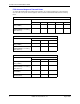
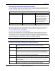
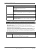
Foundry IronPoint 250 Installation Guide FCC Antenna Usage and Transmit Power To comply with FCC/Canada telecommunication regulation, the conducted output power of this transmitter, when use with each specific antenna supplied, cannot exceed the maximum limit indicated in the following tables. 802.11a RF Power Table for FCC External Antenna Maximum Conducted Transmit Power (dBm) 5180 MHz 5240 MHz 5745 MHz 5785 MHz 5825 MHz 4.5 dBi Integrated Antenna (FDS_2FED02) 11.64 14.91 24.6 24.9 25.
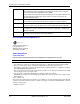
Compliances 802.11g RF Power Table for FCC External Antenna Maximum Conducted Transmit Power (dBm) 2412 MHz 2437 MHz 2462 MHz 2 dBi Integrated Antenna (FDS_2FED02) 21.1 24.5 17.68 6 dBi Omnidirectional Antenna (MMO24580608) (not including 1 dBi cable loss) 19.4 24 17.2 4 dBi Bi-Directional Antenna (MHA2400PT) 19.4 24 16.7 21.75 11.6 13 dBi Directional Panel Antenna 15.
Foundry IronPoint 250 Installation Guide EC Declaration of Conformity 0560 Contact Foundry Networks at: Foundry Networks, Inc. 4980 Great America Parkway Santa Clara, CA 95054 Marking by the above symbol indicates compliance with the Essential Requirements of the R&TTE Directive of the European Union (1999/5/EC).
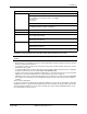
Compliances Operation Using 5 GHz Channels in the European Community The user/installer must use the provided configuration utility to check the current channel of operation and make necessary configuration changes to ensure operation occurs in conformance with European National spectrum usage laws as described below and elsewhere in this document. Allowed 5GHz Channels in Each European Community Country Allowed Frequency Bands Allowed Channel Numbers Countries 5.15 - 5.
Foundry IronPoint 250 Installation Guide German Hiermit erklärt Foundry Networks, dass sich dieser/diese/dieses Radio LAN device in Übereinstimmung mit den grundlegenden Anforderungen und den anderen relevanten Vorschriften der Richtlinie 1999/5/EG befindet". (BMWi) Hiermit erklärt Foundry Networks die Übereinstimmung des Gerätes Radio LAN device mit den grundlegenden Anforderungen und den anderen relevanten Festlegungen der Richtlinie 1999/5/EG.
Compliances Power Cord Set U.S.A. and Canada The cord set must be UL-approved and CSA certified. The minimum specifications for the flexible cord are: - No. 18 AWG - not longer than 2 meters, or 16 AWG. - Type SV or SJ - 3-conductor The cord set must have a rated current capacity of at least 10 A The attachment plug must be an earth-grounding type with NEMA 5-15P (15 A, 125 V) or NEMA 6-15P (15 A, 250 V) configuration. Denmark The supply plug must comply with Section 107-2-01, Standard DK2-1a or DK2-5a.
Foundry IronPoint 250 Installation Guide Cordon électrique - Il doit être agréé dans le pays d’utilisation Etats-Unis et Canada: Le cordon doit avoir reçu l’homologation des UL et un certificat de la CSA. Les spécifications minimales pour un cable flexible sont AWG No. 18, ou AWG No. 16 pour un cable de longueur inférieure à 2 mètres. - type SV ou SJ - 3 conducteurs Le cordon doit être en mesure d’acheminer un courant nominal d’au moins 10 A.
Contents Compliances . . . . . . . . . . . . . . . . . . . . . . . . . . . . . . . . . . . . . . . . . . . . . . . . . . . . . . . . . . . . . . . . . . . .iii Chapter 1. About This Guide . . . . . . . . . . . . . . . . . . . . . . . . . . . . . . . . . . . . . . . . . . . . . . . . . . . . . . . . . . . . . . .1-1 Audience . . . . . . . . . . . . . . . . . . . . . . . . . . . . . . . . . . . . . . . . . . . . . . . . . . . . . . . . . . . . . . . . . . .1-1 Nomenclature . . . . . . . . . . . . . . . . . .
Foundry IronPoint 250 Installation Guide Features and Benefits . . . . . . . . . . . . . . . . . . . . . . . . . . . . . . . . . . . . . . . . . . . . . . . . . . . . . . . . .2-7 Connectivity . . . . . . . . . . . . . . . . . . . . . . . . . . . . . . . . . . . . . . . . . . . . . . . . . . . . . . . . . . . . . .2-7 Management . . . . . . . . . . . . . . . . . . . . . . . . . . . . . . . . . . . . . . . . . . . . . . . . . . . . . . . . . . . . .2-7 Chapter 3. Network Planning . . . . . . . . . . . . . .
Contents Crossover Wiring . . . . . . . . . . . . . . . . . . . . . . . . . . . . . . . . . . . . . . . . . . . . . . . . . . . . . . . . . B-2 Console Port Pin Assignments . . . . . . . . . . . . . . . . . . . . . . . . . . . . . . . . . . . . . . . . . . . . . . . . . B-3 Wiring Map for Serial Cable . . . . . . . . . . . . . . . . . . . . . . . . . . . . . . . . . . . . . . . . . . . . . . . . B-3 Appendix C. Specifications . . . . . . . . . . . . . . . . . . . . . . . . . . . . . . . . . . . . . . . . .
Foundry IronPoint 250 Installation Guide xiv © 2007 Foundry Networks, Inc.
Chapter 1 About This Guide The IronPoint™ 250 Access Point is a device that allows wireless clients to connect to your enterprise network. It is a full-featured access point that can be managed as a single device. This guide presents the procedures for installing the IronPoint™ 250 Access Point. Audience This guide is for system administrators with a working knowledge of wireless networks and network management. You should be familiar with switching and networking concepts.
Foundry IronPoint 250 Installation Guide Web Access Point your browser to the kp.foundrynet.com to access the Foundry Knowledge Portal. Note: Check with your sales account representative to determine how to obtain a valid user name and password for the Foundry Knowledge Portal. E-mail Access Technical requests can also be sent to the e-mail address: support@foundrynet.com Telephone Access ◆ 1.877.TURBOCALL (887.2622): United States ◆ 1.408.586.
Chapter 2 About the IronPoint 250 Overview Foundry’s IronPoint 250 is an IEEE 802.11a/g enterprise wireless access point that provides highspeed data communications between the wired LAN and fixed, portable or mobile devices equipped with an 802.11a, 802.11b, or 802.11g wireless network card. The access point offers full network management capabilities through a command line interface for initial configuration and troubleshooting, a Web interface, and Simple Network Management tools. Figure 2-1.
Foundry IronPoint 250 Installation Guide Radio Characteristics The IEEE 802.11a/g standard uses a radio modulation technique known as Orthogonal Frequency Division Multiplexing (OFDM), and a shared collision domain (CSMA/CA). It operates at the 5 GHz Unlicensed National Information Infrastructure (UNII) band for connections to 802.11a clients, and at 2.4 GHz for connections to 802.11g clients. IEEE 802.11g includes backward compatibility with the IEEE 802.11b standard. IEEE 802.11b also operates at 2.
About the IronPoint 250 Description of Hardware Ethernet Port The access point has one 10BASE-T/100BASE-TX RJ-45 Ethernet port that can be attached directly to a 10BASE-T/100BASE-TX/1000BASE-T wired network. The wired network must conform to the IEEE 802.3-2005 specifications. The Ethernet port supports automatic MDI/MDI-X operation, so you can use straight-through cables for all network connections to PCs, switches, or hubs.
Foundry IronPoint 250 Installation Guide Figure 2-2. An Example of an Optional External Antenna 2-4 © 2007 Foundry Networks, Inc.
About the IronPoint 250 Status LEDs The access point includes four status LED indicators, as described in the following figure and table. Figure 2-3. Status LEDs Ethernet Link/Activity Power 802.11a Wireless Link/Activity 802.11b/g Wireless Link/Activity Status LEDs LED Status Description Status On Green Indicates that power is being supplied and the system is working normally.
Foundry IronPoint 250 Installation Guide Security Slot The access point includes a Kensington security slot on the rear panel. You can prevent unauthorized removal of the access point in several ways: by wrapping Foundry’s locking clamp (lock not provided) or by using a Kensington security cable (not provided). Console Port This port is used to connect a console device to the access point through a serial cable. This connection is described under “Console Port Pin Assignments” on page B-3.
About the IronPoint 250 Features and Benefits Connectivity ◆ 54 Mbps wireless interface supports up to 64 mobile users ◆ Local network connection via 10/100 Mbps Ethernet port ◆ IEEE 802.11a, 802.11b, and 802.11g compliant on the wireless interfaces ◆ IEEE 802.3-2005 compliant on the Ethernet interface ◆ Ethernet port supports Power over Ethernet based on the IEEE 802.3af standard ◆ Provides seamless roaming within the IEEE 802.11a, 802.11b, and 802.
Foundry IronPoint 250 Installation Guide 2-8 © 2007 Foundry Networks, Inc.
Chapter 3 Network Planning Network Topologies The IronPoint 250 supports an integrated configuration with 10/100 Mbps Ethernet LANs. One or more access points can be configured as: • Infrastructure for wireless LANs • Infrastructure wireless LAN for roaming wireless PCs The 802.11b and 802.11g frequency band which operates at 2.4 GHz can easily encounter interference from other 2.4 GHz devices, such as other 802.11b or g wireless devices, cordless phones and microwave ovens.
Foundry IronPoint 250 Installation Guide Infrastructure Wireless LAN The IronPoint 250 is designed to provide access to a wired LAN for wireless workstations. An integrated wired/wireless LAN is called an Infrastructure configuration. A Basic Service Set (BSS) consists of a group of wireless PC users and an access point that is directly connected to the wired LAN.
Network Planning continuous coverage area is created, wireless users within this ESS can roam freely. All wireless network cards and access points within a specific ESS must be configured with the same SSID. Figure 3-2. Wireless LAN Roaming Server Desktop PC Notebook with Wireless PC Card Adapter Switch Access Point Notebook with Wireless PC Card Adapter Switch Access Point Seamless Roaming PC with Wireless PCI Adapter August 2007 © 2007 Foundry Networks, Inc.
Foundry IronPoint 250 Installation Guide 3-4 © 2007 Foundry Networks, Inc.
Chapter 4 Installing the IronPoint 250 Access Point This section presents procedures for installing the IronPoint 250 access point.
Foundry IronPoint 250 Installation Guide CAUTION: When mounting the access point on a wall or suspended ceiling, use PoE power ONLY. Do not use the AC power adapter. Note: For safety reasons, make sure ventilation holes on the access point are positioned horizontally, not vertically. Allow at least 1 inch (2.54 centimeters) clearance around the ventilation holes for proper ventilation.
Installing the IronPoint 250 Access Point access point must be mounted with the RJ-45 cable connector oriented upwards to ensure proper operation. Do the following to attach the access point to the wall using the mounting bracket: 1. Using the mounting bracket, mark the position of the four screw holes on the wall. For concrete or brick walls, you will need to drill holes and insert wall plugs for the screws. 2.
Foundry IronPoint 250 Installation Guide axes, providing the same coverage. For example, if the access point is mounted on a horizontal surface, both antennas should be positioned pointing vertically up to provide optimum coverage. Attaching the Access Point to a Suspended Ceiling To mount the access point to a suspended ceiling T-rail (Figure 4-4), do the following: 1. Attach the plastic ceiling tile mounting clamp to the mounting bracket (Figure 4-3) using the two included screws.
Installing the IronPoint 250 Access Point Figure 4-4. Attaching the Bracket to a Suspended Ceiling Position T-rail between mounting holders Push access point up onto T-rail, then turn Clips lock T-rail into mounting holders Locking the Access Point To prevent unauthorized removal of the access point, you can use a Kensington Slim MicroSaver security cable (not included) to attach the access point to a fixed object.
Foundry IronPoint 250 Installation Guide specific antenna and cable combinations. For this reason, you must consult with a professional installer who is trained in RF installation and knowledgeable in the local regulations prior to connecting an external antenna to your wireless radio product. It is the responsibility of the end user to ensure that the antenna installation complies with the local radio regulations. To install an external antenna: 1.
Installing the IronPoint 250 Access Point 3. On your PC console application configure the following communication parameters: • 9600 bits per second • 8 data bits • No parity • 1 stop bits • No Flow Control 4. Connect the power adapter cable to the 48V DC power socket on the access point and the other end of the cable to a power source. CAUTION: Use ONLY the power adapter supplied with this access point. Otherwise, the product may be damaged.
Foundry IronPoint 250 Installation Guide attached to the IronPoint-FES, the switch assigns the predefined IP address, subnet mask, and default gateway to the access point with the matching MAC address. The IronPoint 250 is shipped with the ADC feature enabled. If you want to use ADC to configure TCP/IP address information, refer to the Foundry IronPoint Wireless LAN Configuration Guide for the IronPoint-FastIron Edge Switch for details.
Installing the IronPoint 250 Access Point US-UNITED_STATES, UY-URUGUAY, VE-VENEZUELA, VN-VIETNAM 5. Configure the TCP/IP address. The default IP address for the access point is 169.254.1.1 with a 255.255.0.0 subnet mask and a default gateway of 169.254.1.254. To change the access point's IP address, for example, to 192.168.1.10 with a 24-bit subnet mask and a default gateway of 192.168.1.
Foundry IronPoint 250 Installation Guide 9. Connect the other end of the cable to the network subnet for which the access point was programmed. 10. Power up the access point. It can now be managed using its command line interface (CLI) or Web interface. Once the access point is set up with country code and IP address, other parameters can be defined using one of the following methods: • A PC running Internet Explorer version 5.
Chapter 5 Making a Network Connection Connecting to a Network Device The IronPoint 250 is designed to connect a wired Ethernet network to wireless clients. It can be connected to any Ethernet network device, such as a hub or switch. CAUTION: The IronPoint 250 is only intended for installation in Environment A as defined in IEEE 802.3af. All interconnected equipment must be contained within the same building, including the interconnected equipment's associated LAN connection.
Foundry IronPoint 250 Installation Guide Connecting to a Switch, Hub, PC, or Server 1. Attach one end of a twisted-pair cable segment to the network device’s RJ-45 connector. Figure 5-1. Connecting to a Network Device 2. Attach the other end of the cable segment to the Ethernet port on the access point. Note: Make sure the twisted pair cable does not exceed 100 meters (328 ft) in length. 3. As the connection is made, the access point’s Link LED should light indicating a valid network connection.
Appendix A Troubleshooting Diagnosing Access Point Indicators Troubleshooting Chart Symptom Action Status LED is Off • External power supply may be disconnected. Check connections between the access point, the power adapter, and the wall outlet. • If using PoE, verify that access point’s RJ-45 port is attached to a PoE source device, that the PoE source device is powered on, and that PoE power is enabled on the port attached to the access point. • Contact Technical Support.
Foundry IronPoint 250 Installation Guide In-Band Access If the access point cannot be configured using the CLI via Telnet or SSH v2, a Web browser using HTTP or HTTPS, or SNMP v2 or v3 software, check the following items before you contact Technical Support.
Troubleshooting • Check the configuration matrix for the most commonly used authentication and encryption combinations in the Quick Installation and Getting Started Guide to ensure that the access point is correctly configured. Lost Password The only way to recover a lost password is by setting the access point to its default configuration. Refer to the section “Reset the Access Point Default Settings” for instructions.
Foundry IronPoint 250 Installation Guide A-4 © 2007 Foundry Networks, Inc.
Appendix B Cables Specifications Cable Types and Specifications Cable Type Max. Length Connector 10BASE-T Cat. 3 or better 100-ohm UTP 100 m (328 ft) RJ-45 100BASE-TX Cat. 5 or better 100-ohm UTP 100 m (328 ft) RJ-45 Twisted-Pair Cable and Pin Assignments CAUTION: DO NOT plug a phone jack connector into any RJ-45 port. Use only twisted-pair cables with RJ-45 connectors that conform with FCC standards. For 100BASE-TX/10BASE-T connections, a twisted-pair cable must have two pairs of wires.
Foundry IronPoint 250 Installation Guide 100BASE-TX/10BASE-T Pin Assignments Use unshielded twisted-pair (UTP) or shielded twisted-pair (STP) cable for RJ-45 connections: 100-ohm Category 3 or better cable for 10 Mbps connections, or 100-ohm Category 5 or better cable for 100 Mbps connections. Also be sure that the length of any twisted-pair connection does not exceed 100 meters (328 feet).
Cables Figure B-3. Crossover Wiring EIA/TIA 568B RJ-45 Wiring Standard 10/100BASE-TX Crossover Cable White/Orange Stripe Orange 1 2 3 4 5 6 7 8 End A White/Green Stripe Blue White/Blue Stripe Green White/Brown Stripe 1 2 3 4 5 6 7 8 End B Brown Console Port Pin Assignments The DB-9 serial port on the IronPoint 250 is used to connect to the access point for out-of-band management. The access point’s command-line interface can be accessed from a terminal or a PC running a terminal emulation program.
Foundry IronPoint 250 Installation Guide The serial port’s configuration requirements are as follows: B-4 • Default Baud rate—9,600 bps • Character Size—8 Characters • Parity—None • Stop bit—One • Data bits—8 © 2007 Foundry Networks, Inc.
Appendix C Specifications General Specifications Maximum Channels 802.11a: US & Canada: 10 (normal mode), 3 (turbo mode) Japan: 4 (normal mode), 1 (turbo mode) ETSI: 4 channels (normal mode), 1 (turbo mode) Taiwan: 4 (normal mode), 1 (turbo mode) 802.11g: FCC/IC: 1-11 ETSI: 1-13 France: 10-13 MKK: 1-14 Taiwan: 1-11 Maximum Clients 64 per VAP interface Operating Range See “Maximum Distance Tables” on page C-5.” Data Rate 802.
Foundry IronPoint 250 Installation Guide 5.50 ~ 5.70 GHz Europe 5.25 ~ 5.35 GHz (middle band) Taiwan 5.725 ~ 5.825 GHz (high band) Taiwan 802.11b/g: 2.4 ~ 2.4835 GHz (US, Canada, ETSI) 2.4 ~ 2.497 GHz (Japan) 2.400 ~ 2.4835 GHz (Taiwan) AC Power supply Input: 100-240 VAC, 50-60 Hz Output: 48 VDC, 0.38 A Unit Power Supply DC Input: 48 VDC, 0.38 A maximum Input voltage: 48 volts, 0.27 A, 12.95 watts Power consumption: 9.6 watts maximum PoE (DC) Input voltage: -48 VDC, 0.27 A, 12.
Specifications Radio Signal Certification FCC Part 15, Subpart C - Intentional Radiators 15.247, 15.207, 15.407 RSS-210 (Canada) RSS-102 (Canada) EN 300 328, EN 300 893, EN 301 489 (Sections 1-17, as necessary) (Europe) ARIB STD 33 (Japan) ARIB STD 66 (Japan) ARIB STD T71 (Japan) AS/NZS 4771, 4628.2 (Australia and New Zealand) Safety UL/CUL (CSA 22.2 No. 60950-1 & UL60950-1) EN 60950-1 (TÜV/GS) IEC 60950-1 (CB) Standards IEEE 802.3-2005 IEEE 802.11a, b, g August 2007 © 2007 Foundry Networks, Inc.
Foundry IronPoint 250 Installation Guide Sensitivity IEEE 802.11a Modulation/Rates Sensitivity (GHz - dBm) 5.15-5.250 5.25-5.350 5.50-5.700 5.725-5.825 BPSK (6 Mbps) -88 -88 -88 -88 BPSK (9 Mbps) -87 -87 -87 -87 QPSK (12 Mbps) -86 -86 -86 -86 QPSK (18 Mbps) -83 -83 -83 -83 16 QAM (24 Mbps) -80 -80 -80 -80 16 QAM (36 Mbps) -76 -76 -76 -76 64 QAM (48 Mbps) -73 -73 -73 -73 64QAM(54 Mbps) -70 -70 -70 -70 IEEE 802.
Specifications Maximum Distance Tables Important Notice The operating range distances listed in the following tables are for typical environments only. Operating ranges can vary considerably depending on factors such as local interference and barrier composition. It is recommended to do a site survey to determine the maximum ranges for specific access point locations in your environment. 802.
Foundry IronPoint 250 Installation Guide C-6 © 2007 Foundry Networks, Inc.
Appendix D Cautions and Warnings The cautions and warnings that appear in this manual are listed below in English, German, French, and Spanish. Cautions A caution calls your attention to a possible hazard that can damage equipment. "Vorsicht” weist auf die Gefahr einer möglichen Beschädigung des Gerätes in. Une mise en garde attire votre attention sur un risque possible d'endommagement de l'équipement. Ci-dessous, vous trouverez les mises en garde utilisées dans ce manuel.
Foundry IronPoint 200 Installation Guide D-2 PRECAUCIÓN: No enchufe una clavija de teléfono en un puerto RJ-45. Utilice solamente cables de par trenzado con conectores RJ-45 que se ajusten a la normativa FCC. CAUTION: Each wire pair must be attached to the RJ-45 connector in a specific orientation. VORSICHT: Jedes Leiterpaar muss in einer bestimmten Ausrichtung am RJ-45-Anschluss angeschlossen werden.
Cautions and Warnings CAUTION: The IronPoint 250 is only intended for installation in Environment A as defined in IEEE 802.3af. All interconnected equipment must be contained within the same building, including the interconnected equipment's associated LAN connection. VORSICHT: IronPoint 250 ist nur zur Installation in einer Umgebung A, wie in IEEE 802.3af definiert, bestimmt.
Foundry IronPoint 200 Installation Guide ADVERTENCIA Este producto es adecuado para su uso en el espacio aéreo circundante en conformidad con la sección 300-22(c) del National Electric Code (Código Eléctrico Nacional de EE.UU.) y las secciones 2- 128.12 - 010 (3) y 12 - 100 del Código Eléctrico de Canadá. Parte 1. C22. 1. En otros países, consulte a las autoridades locales competentes para informarse acerca de las normativas vigentes.
Glossary 10BASE-T IEEE 802.3 specification for 10 Mbps Ethernet over two pairs of Category 3 or better UTP cable. 100BASE-TX IEEE 802.3u specification for 100 Mbps Fast Ethernet over two pairs of Category 5 or better UTP cable. Access Point An internetworking device that seamlessly connects wired and wireless networks. Access points attached to a wired network, support the creation of multiple radio cells that enable roaming throughout a facility.
Foundry IronPoint 250 Installation Guide Dynamic Host Configuration Protocol (DHCP) Provides a framework for passing configuration information to hosts on a TCP/IP network. DHCP is based on the Bootstrap Protocol (BOOTP), adding the capability of automatic allocation of reusable network addresses and additional configuration options.
Glossary LED Light emitting diode used for monitoring a device or network condition. Local Area Network (LAN) A group of interconnected computer and support devices. MAC Address The physical layer address used to uniquely identify network nodes. Power over Ethernet (PoE) A specification for providing both power and data to low-power network devices using a single Category 5 Ethernet cable.
Foundry IronPoint 250 Installation Guide Glossary-4 © 2007 Foundry Networks, Inc.
Index Numerics E 100BASE-TX ports 2-3 10BASE-T ports 2-3 Ethernet connection 5-1 A air flow requirements 4-2 antennas, positioning 4-2, 4-3 applications 3-1 infrastructure 3-2 wireless LAN roaming 3-2 B Basic Service Set See BSS bracket, wall mount 4-2 BSS 3-2 C cable crossover B-2 specifications B-1 straight-through B-2 channels, maximum C-1 clients, maximum C-1 console cable 2-2 console port 2-2, 2-6 pin assignments B-3 crossover cable B-2 CSMA/CA 2-2 D data rate, options C-1 desktop mounting 4-2
Foundry IronPoint 250 Installation Guide on a desktop or shelf 4-2 N network connections 5-1 topologies 3-1 network topologies 3-1 infrastructure 3-2 infrastructure for roaming 3-2 null-modem serial cable 2-2 O telephone 1-2 Web 1-2 troubleshooting in-band access A-2 switch indicators A-1 twisted-pair connections 5-1 W wall mounting bracket 4-2 Web-based management 2-2 wireless LANs infrastructure 3-2 roaming 3-2 OFDM 2-2 operating frequency C-1 out-of-band management 2-2 P password, support 1-2 pin