Foundry NetIron M2404C and M2404F Metro Access Switches Installation Guide ™ 4980 Great America Parkway Santa Clara, CA 95054 Tel 408.207.1700 www.foundrynetworks.
Copyright © 2007 Foundry Networks, Inc. All rights reserved. No part of this work may be reproduced in any form or by any means – graphic, electronic or mechanical, including photocopying, recording, taping or storage in an information retrieval system – without prior written permission of the copyright owner. The trademarks, logos and service marks ("Marks") displayed herein are the property of Foundry or other third parties.
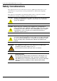
Foundry NetIron M2404C/M2404F Metro Access Switches Safety Considerations This equipment is for use in a restricted access area by qualified personnel only. To avoid electric shock, do not perform any servicing other than those contained in the unpacking instructions. This equipment contains Electrostatic Discharge (ESD) sensitive components. Use ESD protection before servicing or installing components of this system.
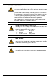
Foundry NetIron M2404C/M2404F Metro Access Switches WARNING GROUNDING Before connecting the product to the power line, make sure that the protective ground terminal of the device is connected to the safety ground conductor of the mains power cord. The main power supply plug should only be inserted in a socket outlet provided with a connected safety ground. The protective action must not be negated by use of an extension cord (power cable) without a protective conductor (grounding).
Foundry NetIron M2404C/M2404F Metro Access Switches Table of Contents ABOUT THIS DOCUMENT......................................................................................... 1 WHO SHOULD USE THIS GUIDE ..................................................................................... 1 HOW THIS DOCUMENT IS ORGANIZED ........................................................................... 1 CONVENTIONS USED IN THIS DOCUMENT ......................................................................
Foundry NetIron M2404C/M2404F Metro Access Switches SOFTWARE IMAGE NAMING CONVENTIONS ................................................................. 26 DOWNLOADING A SOFTWARE IMAGE TO THE SWITCH USING TFTP ............................ 26 Preparing to Download an Image Using TFTP...................................................... 26 Downloading a Device Software Image Using TFTP............................................. 26 Downloading a NI-M2404WebView Image Using TFTP .............................
Foundry NetIron M2404C/M2404F Metro Access Switches About This Document Who Should Use This Guide The procedures in this manual are for trained and qualified service personnel who are proficient with network switching and routing concepts. Installation, replacement and maintenance of the equipment described in this guide may only be done by trained and qualified service personnel. How This Document is Organized This document contains the following chapters. January 2007 Chapter Contains 1.
Foundry NetIron M2404C/M2404F Metro Access Switches Conventions Used in this Document This document uses the following formatting styles and conventions: • CLI syntax and coded examples are represented by mono-space characters and enclosed in rectangular frames. Under this category: o Text issued by the device software is represented by regular characters.
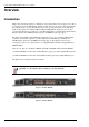
Foundry NetIron M2404C/M2404F Metro Access Switches Overview Introduction High powered networks require a combination of speed and robust services support to be able to provide the intensive and fluctuating demands of their end users. To answer these requirements, the network needs to provide data transmission at wire speed performance in a non-blocking fashion.
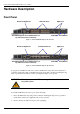
Foundry NetIron M2404C/M2404F Metro Access Switches Hardware Description Front Panel Enhanced GigE Ports 100baseX Ports Switch Management Ports (Outband Port on top and Console Port on bottom) GigE Ports PSU LEDs Reset Button Figure 3: NetIron M2404F Platform Front Panel Enhanced GigE Ports 10/100baseTX Ports Switch Management Ports (Outband Port on top and Console Port on bottom) GigE Ports PSU LEDs Reset Button Figure 4: NetIron M2404C Platform Front Panel To prepare for installation, make
Foundry NetIron M2404C/M2404F Metro Access Switches 3. Gently insert the SFP tranceiver into the port until the module clicks into place. The module is keyed to prevent incorrect insertion. See Figure 5. Important Note When inserting an SFP tranceiver into ports marked 27 or 28, verify that the SFP is facing upside -down (as shown in figure below). All other SFP ports on the switch face right-side up.
Foundry NetIron M2404C/M2404F Metro Access Switches Component Description GigE Dual-Mode Ports Two dual-mode1000baseX interface (SFP) or 10/100/1000BaseT (RJ45) marked 25 and 26. Enhanced GigE Ports Two 1000baseX interface (SFP) marked 27 and 28. Please note that the SFP transceivers are inserted into the slot, belly-down, as shown in figure above. Console Management Port RJ45 socket for CLI configuration and management of the unit.
Foundry NetIron M2404C/M2404F Metro Access Switches Port Status LEDs A status LED is associated with each port. Port Status Indication Link Green Activity Blinking green Fault/disabled Amber NetIron M2404C Port Status LEDs Port 1 Port 3 Port 5 Port 7 Port 9 Port 2 Port 4 Port 6 Port 8 Port 10 Port 12 Port 11 Figure 6: Location of NetIron M2404C Port Status LEDs The port status LEDs (1 to 24) for NetIron M2404C are situated on the upper row of ports.
Foundry NetIron M2404C/M2404F Metro Access Switches NetIron M2404F Dual-Mode Port Status LEDs Figure 8: Location of NetIron M2404F Dual-Mode Port Status LEDs Dual-mode port status LEDs are associated with dual-mode RJ45/SFP GiGE ports 25 and 26.
Foundry NetIron M2404C/M2404F Metro Access Switches Rear Panel – with AC Power-Supply Units Hot-swappable PSU #2 On-off switch Fan apertures AC-Power inlet Grounding studs Hot-swappable PSU #1 On-off switch AC-Power inlet Figure 9: Rear Pane l with AC PSUs Panel Main Components January 2007 Two AC Power supplies As specified in Power Supply Units. Two grounding posts Designed for a UL-listed two-hole long-barrel 5/8 10 AWG compression lug. Burndy YAZV10-2TC14 or an equivalent is recommended.
Foundry NetIron M2404C/M2404F Metro Access Switches Rear Panel – with DC Power-supply Units Hot-swappable PSU #2 Terminal block Fan apertures PWR and Invert. Con. LEDs Grounding studs Hot-swappable PSU #1 Terminal block PWR and Invert. Con. LEDs Figure 10: Rear Panel with DC PSUs Panel Main Components Two DC Power supplies As specified in Power Supply Units. Two grounding posts Designed for a UL-listed two-hole long-barrel 5/8 10 AWG compression lug.
Foundry NetIron M2404C/M2404F Metro Access Switches DC power-supply terminals: LEDs: -48V/3A GND +BAT.RET INVERT CON. PWR Figure 12: DC Power Supply Unit The DC power supply panel has the following components: Input terminals: -48V/3A Negative DC input terminal GND Ground terminal internally connected to the platform’s ground line +BAT.RET Positive DC input terminal NOTE Neither the +BAT.RET nor the -48VDC is connected to the GND terminal.
Foundry NetIron M2404C/M2404F Metro Access Switches Figure 13 Blank Filler for Empty Power-Supply Slot January 2007 © 2007 Foundry Networks, Inc.
Foundry NetIron M2404C/M2404F Metro Access Switches Installation and Setup This section provides installation and setup instructions. The platform can be installed in a standard 19-inch rack or as a standalone unit in a desktop configuration. Packing List The shipping package includes the following items: • NetIron M2404F /NetIron M2404C platform. • One AC (ACPS) or DC (DCPS) power-supply unit, installed. • One power cable.
Foundry NetIron M2404C/M2404F Metro Access Switches WARNING Make sure the rack or cabinet housing the device is adequately secured to prevent it from becoming unstable or falling over. Rack Mounting Specifications Width Basic body: 440 mm (17.4”) Overall, including brackets: 483 mm (19”) Height 44 mm (1.73”) = 1 RU Depth 414 mm (16.3”) Distance between mounting holes Horizontal: 465 mm (18.3”) Vertical: 31.75 mm (1.25”) Vertical separation: 12.7 mm (0.
Foundry NetIron M2404C/M2404F Metro Access Switches Ethernet Cables When connecting an RJ-45/RJ-48 port to an end station, workstation or server, use a standard RJ-45/RJ-48 pin-out cable. Console Interface A simple menu-driven interface provides for system initialization and diagnostics. The Console interface is EIA232 VT-100 compatible. The primary purpose of the terminal interface is to set basic operational parameters. The terminal interface is password protected.
Foundry NetIron M2404C/M2404F Metro Access Switches For each DC power block a set of a minimum 2x18AWG cables shall be used with suitable end terminal legs matching the conductor’s gauge. Use a RED lead to for the positive conductor and a BLACK lead for the negative conductor. It is recommended that only UL listed components be used for the DC power connections. CAUTION For a DC system, use a grounding wire of at least 10 American Wire Gauge (AWG).
Foundry NetIron M2404C/M2404F Metro Access Switches 2. Remove the bolts and spring-washers from the grounding posts on the switch’s rear panel, and clean the metal surface underneath with a dry cloth if necessary. 3. Apply some anti-oxidant onto the metal surface. 4. Mount the lug on the two grounding posts, replace the spring-washers and fasten the bolts. Avoid using excessive torque. 5. Connect the grounding wire to a reliable ground.
Foundry NetIron M2404C/M2404F Metro Access Switches Initial Configuration Using the Console Initial Configuration The Configuration command-language interface (CLI) is accessed by using a VT-100 (or compatible terminal) to the console port of the switch. The terminal port parameters are fixed at: 9600 bps, 8 data bits, 1 stop bit, no parity and without flow control. This provides a convenient method for initial setup of the switch. System parameters are stored in a non-volatile memory.
Foundry NetIron M2404C/M2404F Metro Access Switches quit show terminal who Disconnect and logout Show running system information Terminal configuration setup Display who is on vty To continue initial configuration procedure perform the following steps: 1. Enter privileged (Enable) mode. Type the command: enable. 2. Enter configure mode. Type the command: configure terminal. 3. Set the switch IP address: Type the command: ip address , where
Foundry NetIron M2404C/M2404F Metro Access Switches application java running-config startup-config Application downloading image Java downloading image Copy running config... Startup configuration data To write the backup configuration file, type: device-name#copy startup-config is the file where the configuration file was saved. Downloading Configuration from Backup Text File The configuration file can be easily downloaded, using the copy command.
Foundry NetIron M2404C/M2404F Metro Access Switches Temperature Management Commands Viewing the Status: device-name#show temperature CPU Temperature = 28C / 82F device-name#show temperature high-limit CPU Temperature high limit = 20C / 68F Configuring Temperature Management Parameters: device-name#configure terminal device-name(config)#monitor temperature device-name(config monitor temperature C)#limit NUMBER Value of limit for alerting current test device-name(config monitor temperature C)#limit 70 View
Foundry NetIron M2404C/M2404F Metro Access Switches Monitoring the Power Supplies Status Viewing the status during system boot: BUILT-IN SELF TEST -----------------CPU Core Test CPU Interface Test Data Buffer Test Power Supply Test On-board Power Test Fan Test : : : : : : Passed Passed Passed Passed Passed Passed Viewing the status during operation: The Power Supply status is available on the DC and dual-feed AC models only. The possible values are OK, Failed, and Not Installed.
Foundry NetIron M2404C/M2404F Metro Access Switches Built-In Self Test (BIST) The BIST performs a set of basic hardware and configuration validity tests. Tests in the BIST are sorted into several groups – for example, the tests of the Power Supply units belong to a Power Supply Test group. Startup BIST - The BIST is performed automatically on startup. The results are summarized on the terminal before the switch banner. BIST by request - A user may request BIST execution at any time by using a CLI command.
Foundry NetIron M2404C/M2404F Metro Access Switches 2. Re-power the unit, if required. 3. Use the show self-test command in Privileged (Enable) mode. If you prefer to display all BIST results, use the show self-test full command instead. To invoke a BIST by Request at any time while the switch is running, use the self-test command in Privileged (Enable) mode. The switch will automatically start up in debug mode when one of the five On-Board power levels deviates by 2% above or below the required level.
Foundry NetIron M2404C/M2404F Metro Access Switches //////////////////////////////////////////////////////////////////// //................................................................// // FOUNDRY NETWORKS // // // // Switch model : FOUNDRY NETWORKS NETIRON M2404F 256M // // SW version : 2.0.
Foundry NetIron M2404C/M2404F Metro Access Switches Software Download The executable software image contained on the platform can be upgraded via the network whenever new versions become available, reflecting changes in the MIBs or enhancements to the software. The software is stored in erasable Flash memory. It must be downloaded using the Trivial File Transfer Protocol (TFTP). Software Image Naming Conventions Table 2 displays an example of typical software image names.
Foundry NetIron M2404C/M2404F Metro Access Switches 1. Copy the device software image file to the appropriate TFTP directory on the workstation. 2. Log into the switch through the console port or through a Telnet session. If you log in using Telnet, your Telnet session will disconnect when you reset the switch to run the new software. 3. Make sure there is enough free space on the device file system. Use “dir” command for this. Free disk space should be at least 0.
Foundry NetIron M2404C/M2404F Metro Access Switches 6. Configure the switch to boot with the newly downloaded image. This is done by selecting boot application and boot device. device-name#config boot-param device-name(boot param)#application device-name(boot param)#device local device-name(boot param)#exit Example: device-name#config boot device-name(boot param)#application M2404v2.0.bin device-name(boot param)#device local device-name(boot param)#exit 7.
Foundry NetIron M2404C/M2404F Metro Access Switches 1. Copy the software image file to the appropriate TFTP directory on the workstation. 2. Log into the switch through the console port or through a Telnet session. 3. Download the software image from the TFTP server using the copy java command in Privileged (Enable) mode: device-name#copy java [] Example: device-name#copy java tftp://192.192.54.10/NI M2404WebViewL3V3.3.9.
Foundry NetIron M2404C/M2404F Metro Access Switches Hot-swapping a Power Supply The switch has two redundant power supplies, and can be operated when only one power supply is connected and powered on, or with both power supplies active. When both power supplies are active, you can remove or replace one power supply unit without interrupting the operation of the switch. To extract a power-supply unit, release the panel screws on both sides of the unit and draw the unit out of its slot.
Foundry NetIron M2404C/M2404F Metro Access Switches Specifications Physical Specifications Dimensions Width 440 mm (17.4”) Height 44 mm (1.73”) Depth 419 mm (16.5”) Weight Chassis without PSU 3.7 kg (8.2 lbs) Each AC Power Supply 0.6 kg (1.3 lbs) Each DC Power Supply 0.6 kg (1.3 lbs) Operating Conditions AC power source Voltage: 100-120 VAC@ 5A or 200-240VAC@2.
Foundry NetIron M2404C/M2404F Metro Access Switches The equipment is designed for use in indoor applications only.
Foundry NetIron M2404C/M2404F Metro Access Switches FCC 47 CFR: 2003 part 15 subpart B, class A This equipment has been tested and found to comply with the limits for a Class A digital device, pursuant to Part 15 of the FCC Rules. These limits are designed to provide reasonable protection against harmful interference when the equipment is operated in a commercial environment.
Foundry NetIron M2404C/M2404F Metro Access Switches Appendix A: Cautions and Warnings Caution Statements A caution calls your attention to a possible hazard that can damage equipment. "Vorsicht” weist auf die Gefahr einer möglichen Beschädigung des Gerätes in. Une mise en garde attire votre attention sur un risque possible d'endommagement de l'équipement. Ci-dessous, vous trouverez les mises en garde utilisées dans ce manuel.
Foundry NetIron M2404C/M2404F Metro Access Switches energía retirado no se reemplaza, inserte el relleno PSU en blanco provisto en el slot y asegúrelo al panel con los dos tornillos. CAUTION: Changes or modifications made to this device that are not expressly approved by the party responsible for compliance could void the user’s authority to operate the equipment.
Foundry NetIron M2404C/M2404F Metro Access Switches Warning Statements A warning calls your attention to a possible hazard that can cause injury or death. The following are the warnings used in this manual. "Achtung" weist auf eine mögliche Gefährdung hin, die zu Verletzungen oder Tod führen können. Sie finden die folgenden Warnhinweise in diesem Handbuch: Un avertissement attire votre attention sur un risque possible de blessure ou de décès.
Foundry NetIron M2404C/M2404F Metro Access Switches should only be performed by qualified personnel, authorized by Foundry Networks. ACHTUNG: Hochspannung Trennen Sie das Gerät vom Netz, bevor Sie die Abdeckung abnehmen. Alle Einstellungs- und Wartungsarbeiten am geöffneten Gerät dürfen nur von Fachleuten durchgeführt werden, die eine Foundry Networks Zertifizierung nachweisen können. Diese Arbeiten dürfen nur an einem von seiner Stromquelle abgetrennten Gerät erfolgen.
Foundry NetIron M2404C/M2404F Metro Access Switches La prise d’alimentation principale doit être insérée uniquement dans une prise ayant un raccordement à la terre. Cette protection ne doit pas être remise en cause par l’utilisation d’une rallonge (câble d’alimentation) ne possédant pas de mise à la terre. Toute discontinuité du circuit de mise à la terre ou déconnexion de la prise de terre risque de rendre l’utilisation du dispositif dangereuse. Toute interruption intentionnelle est interdite.
Foundry NetIron M2404C/M2404F Metro Access Switches ADVERTENCIA: CABLEADO PARA ENCHUFE DE CORRIENTE NACIONAL Con cada unidad se suministra un cable de alimentación principal según el Código eléctrico nacional (National Electrical Code o NEC) con zócalo IEC moldeado.
Foundry NetIron M2404C/M2404F Metro Access Switches AVERTISSEMENT: Vérifiez que le chassis ou l’armoire incluant l’unité est bien fixé afin qu’il ne devienne pas instable ou qu’il ne risque pas de tomber. ADVERTENCIA: Verifique que el montante o el gabinete que alberga el dispositivo está asegurado adecuadamente para evitar que se haga inestable o que se caiga.