
user manual

Product Overview
September 2007 © 2007 Foundry Networks, Inc. 2 - 5
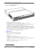
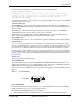
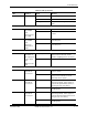
Figure 2.4 shows the front panel of the FGS624P and FGS624P-POE.
Figure 2.4 FGS624P and FGS624P-POE Front Panel
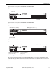
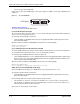
Figure 2.5 shows the front panel of the FGS648P and FGS648P-POE.
Figure 2.5 FGS648P and FGS648P-POE Front Panel
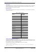
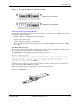
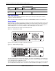
Figure 2.6 shows the front panel of the FGS624XGP and FGS624XGP-POE.
Figure 2.6 FGS624XGP and FGS624XGP-POE Front Panel
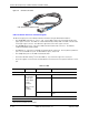
Serial Management Interface (Console Port)
The serial management interface (the port labelled Console) enables you to configure and manage the device
using a third-party terminal emulation application on a directly connected PC. A straight-through EIA/TIA DB-9
serial cable (M/F) ships with the device. The serial management interface is located in the left corner of the front
panel.
1F 2F 3F4F
Console
Lnk
Act
PS1PS2Pwr
5678
1
1
2
2 3
Stack
4
3
4
5
6
7
8
9
10
11
12
13
14
15
16
17
18
19
20
21
22
23
24
Odd
Even
PoE
Lnk-Act
25 26
Lnk
FGS-2XG
Act
Ports 1-4
Ports 25 and 26 Ports 1-24
49
1F 2F 3F 4F
Console
50
Lnk
Act
PS1 PS2 Pwr
5678
1
1
2
23
Stack
4
3
4
5
6
7
8
9
10
11
12
13
14
15
16
17
18
19
20
21
22
23
24
25
26
27
28
29
30
31
32
33
34
35
36
37
38
39
40
41
42
43
44
45
46
47
48
Odd
Even
PoE
Lnk-Act
Lnk
Act
GbE Fiber Ports (1F - 4F)
Optional 2-port 10-GbE Module
(port 49 and 50)
GbE Copper Ports (1 - 48)
1F 2F 3F4F
Console
Lnk
Act
PS1PS2 Pwr
5678
1
1
2
2 3
Stack
4
3
4
5
6
7
8
9
10
11
12
13
14
15
16
17
18
19
20
21
22
23
24
Odd
Even
PoE
Lnk-Act
Lnk
FGS-2XG
Act
Lnk
Act
GbE Fiber Ports (slot 1, ports 1F - 4F) GbE Copper Ports (slot 1, ports 1 - 24)
Optional 2-port 10-GbE Module
(slot 2, ports 1 and 2)
1-port 10-GbE Module
(slot 3, port 1)
Slot 2
12
Slot 3
Slot 1