READ THESE INSTRUCTIONS AND SAVE THEM FOR FUTURE USE Installation Guide Table of Contents: Safety Tips. pg. 1 Unpacking Your Fan. pg. 2 Parts Inventory. pg. 2 Installation Preparation. pg. 3 Hanging Bracket Installation. pg. 3 Fan Assembly. pgs. 4 - 5 Wiring. pg. 6 Canopy Assembly. pg. 7 Blade* Assembly. pg. 7 Light Kit Assembly. pg. 8 Handheld Remote Control Assembly. pg. 9 Automated Learning Process./ Activating Code. pg. 10 Remote Control Operation. pg. 10 Testing Your Fan. pg. 10 Troubleshooting. pg.
SAFETY TIPS. WARNING: To reduce the risk of electrical shock, turn off the electricity to the fan at the main fuse box or circuit panel before you begin the fan installation or before servicing the fan or installing accessories. 1. READ ALL INSTRUCTIONS AND SAFETY INFORMATION CAREFULLY BEFORE INSTALLING YOUR FAN AND SAVE THESE INSTRUCTIONS. CAUTION: To avoid personal injury, the use of gloves may be necessary while handling fan parts with sharp edges. 2. 3. 4.
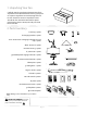
1. Unpacking Your Fan. Carefully open the packaging. Remove items from Styrofoam inserts. Remove motor housing and place on carpet or Styrofoam to avoid damage to finish. Do not discard fan carton or Styrofoam inserts should this fan need to be returned for repairs. Check against parts inventory that all parts have been included. 2. Parts Inventory. b a a. canopy. 1 piece c d b. hanging bracket. 1 piece c. 6in. downrod and hanging ball (with pin and clip). 1 piece e g f d. 4in. downrod. 1 piece e.
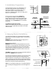
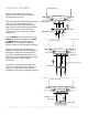
3. Installation Preparation. To prevent personal injury and damage, ensure that the hanging location allows the blades a clearance of 7 feet (2.13m) from the floor and 30in. (76cm) from any wall or obstruction. This fan is suitable for room sizes up to 400 square feet (37.2 square meters). 12ft. - 20ft. (3.66m - 6.1m) blade edge 30 7 feet inches (2.13 m) (76 cm) This fan can be mounted with a downrod on a regular (no-slope) or vaulted ceiling.
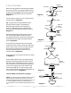
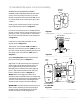
stop pin 5. Fan Assembly. set screw Remove hanging ball from downrod provided by loosening set screw on hanging ball. Remove pin and clip. Lower hanging ball and remove stop pin. Slide hanging ball off of the downrod. [Refer to diagram 1.] hanging ball clip diagram 1 Loosen yoke set screws and nuts at top of motor housing. [Refer to diagram 2.
5. Fan Assembly. (cont.) Remove electrical tape from electrical wiring and thread each of the wires through a different hole in the weatherproof hanging ball cover. Pull weatherproof hanging ball cover down securely over hanging ball (on downrod). [Refer to diagram 5.] weatherproof hanging ball cover electrical wiring set screw hole stop pin WARNING: Failure to tighten set screw on hanging ball completely could result in the fan becoming loose and possibly falling.
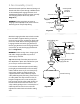
6. Wiring. ground (green or bare) white supply wire WARNING: Turn off circuit breakers to current fixture from breaker panel and be sure switch is turned to the OFF position. black supply wire CAUTION: Be sure outlet box is properly grounded and that a ground wire (GREEN or Bare) is present. blue black black white from ceiling white Make sure all electrical connections comply with Local Codes or Ordinances and the National Electrical Code.
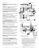
7. Canopy Assembly. Locate 2 screws on underside of hanging bracket and remove screw closest to the open end of the hanging bracket. Partially loosen the other screw. Lift canopy to hanging bracket. Place rounded part of slotted hole in canopy over loosened screw in hanging bracket and push up. Twist canopy to lock. Re-insert screw that was removed and then tighten both screws securely. hanging bracket screw canopy screw 8. Blade Assembly. Remove blade screws/lock washers from underside of motor.
motor housing 9. Light Kit Assembly . Remove 1 screw from motor plate on underside of motor housing and partially loosen the other 2 screws. Align slotted holes in fitter plate with loosened screws in motor plate, allowing molex connectors to come through center hole in fitter plate. Twist fitter plate to lock. Re-insert screw that was previously removed and securely tighten all 3 screws with a Phillips screwdriver.
. Handheld Remote Control Assembly. remote control cover IN ORDER TO USE THE HANDHELD REMOTE CONTROL, PLEASE CONTINUE WITH SECTION 10 for remote control assembly instructions. If you have already installed the wall control but do not wish to use the handheld remote control, please proceed to Section 11. Gently pull on remote control cover to separate top and bottom parts. [Refer to diagram 1.
. Automated Learning Process./Activating Code. CAUTION: The wall and/or handheld remote control can be programmed to multiple receivers or fans. If this is not desired, turn wall switch off to any other programmable receiver or fan. Restore electrical power and then, if using wall control, set slider switch on wall control to the ON position. Within 60 seconds of turning on the wall control, press and hold the OFF button on the wall control for 5 seconds or until light blinks twice.
Troubleshooting. Warranty. WARNING: Failure to disconnect power supply prior to troubleshooting any wiring issues may result in serious injury. Problem: Fan fails to operate. Solutions: 1. Check wall switch to fan/wall control. 2. Check to be sure wall control (optional use) is wired properly. 3. Check to be sure fan is wired properly. 4. Learning process between fan, handheld remote control and, if applicable, wall control may not have been successful and code was not activated.