
Installation Manual


© 2015 Sensata Technologies
Page 17
Installation
2.2.6 Wiring the Inverter to the Battery Bank
CAUTION: The inverter is NOT reverse polarity protected, if this happens the inverter
will be damaged and will not be covered under warranty. Before connecting the DC
wires from the batteries to the inverter, verify the correct battery voltage and polarity
using a voltmeter. If the positive terminal of the battery is connected to the negative
terminal of the inverter and vice versa, severe damage will result. If necessary, color
code the cables (with colored tape): RED for positive (+) and WHITE for negative (–)
to avoid polarity confusion.
Info: The DC overcurrent device (i.e., circuit breaker) must be placed in the positive
(red) DC cable line between the inverter’s positive DC terminal and the battery’s positive
terminal (red); as close to the battery as possible.
DC Ground Wire
Route an appropriately sized DC grounding wire (green or bare wire) from the inverter’s DC
equipment ground terminal (Figure 1-2, Item 7) to a dedicated system ground. Recommended
tightening torque is 45 in lbf (5.1 Nm). Refer to Section 2.4 for grounding information and sizing
the DC ground wires.
DC Negative Wire
Route an appropriately sized DC negative wire (white) from the negative terminal of the battery
bank to the inverter’s negative terminal (Figure 1-2, Item 11).
Info: If installing a battery monitor such as the ME-BMK, install a DC shunt in-line with
the negative battery cable.
DC Positive Wire
Mount the circuit breaker assembly as near as practical to the batteries, and then open the circuit
breaker.
WARNING: DO NOT close the DC circuit breaker to connect battery power to the
inverter at this time. This will occur in the Functional Test after the installation is
complete.
CAUTION: If connecting live battery cables to the inverter’s DC terminals, a brief spark
or arc may occur; this is normal and due to the inverter’s internal capacitors being
charged.
Route and connect an appropriately sized DC positive wire (red) from the inverter’s positive DC
terminal (Figure 1-2, Item 10) to one end of circuit breaker (or DC fuse block).
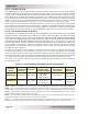
Connect a short wire (same rating as the DC wires) to the other side of the DC circuit breaker
and the other end of the short wire to the positive terminal of the battery bank (see Figure 2-1
for reference).
Ensure the DC wire connections (on the batteries, inverter, and DC circuit breaker) are fl ush
on the surface of the DC terminals, and the hardware (lock washer and nut) used to hold these
connections are stacked correctly (see Figures 2-5 and 2-6). Verify all DC connections are torqued
from 10 to 12 ft lbf (13.6 to 16.3 Nm).
Once the DC connections are completely wired and tested, coat the terminals with an approved
anti-oxidizing spray.
Attach the red and black terminal covers over the inverter’s DC connectors, and then secure them
in place with the supplied screws (see Figure 1-2).
If the batteries are in an enclosure, perform a fi nal check of the connections to the battery terminals,
then close and secure the battery enclosure.