
Installation Manual


© 2015 Sensata Technologies
Page 25
Installation
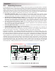
Figure 2-13, Method 1 – DC Ground Rod with Multiple Connections
(using multiple grounding electrodes)
AC
DC Service
Panel
AC Service
Panel
DC Electrical SystemAC Electrical System
Neutral
Positive
Negative
DC
Grounding
System
Negative
SBJ
GC
GEC-AC
EGC-AC
AC Ground DC Ground
SBJ
EGC-DC
GC
Neutral
Hot
GEC-DC
GE GE
GBB GBB
Grounding Electrode
(DC side dedicated)
Grounding Electrode
(AC side dedicated)
MS-PAE Series Inverter/Charger
BC
Method 1 (see Figure 2-13): This method uses a separate grounding electrode (GE) for the
DC system and the AC system. In this method—since there are multiple connections to the DC
grounding electrode (GE)—the size of the DC grounding electrode conductor (GEC–DC) cannot
be smaller than the largest conductor in the DC system (usually the battery-to-inverter cable).
The DC grounding electrode (GE) must be bonded to the AC grounding electrode (GE) to make
a grounding electrode system; this bonding conductor (BC) cannot be smaller than the largest
grounding electrode conductor—either AC or DC.
2.4.1 Sizing the Grounding Electrode Conductors (GEC)
AC Side – The size of the AC grounding electrode conductor (GEC–AC) depends on the size of the
largest ungrounded conductor feeding the AC load center. A #8 AWG (8.4 mm
2
) copper conductor
will serve as an AC grounding electrode conductor for AC power conductors smaller than and
including #2 AWG (33.6 mm
2
) copper. See Table 2-3 for additional values.
Table 2-3, AC Grounding Electrode Conductor (GEC–AC) Sizing
Size of Largest Ungrounded
Conductor (Copper)
Minimum Size of Grounding
Electrode Conductor (Copper)
2 AWG (33.6 mm
2
) or smaller #8 AWG (8.4 mm
2
)
1 AWG (42.4 mm
2
) or 1/0 AWG (53.5 mm
2
) #6 AWG (13.3 mm
2
)
2/0 AWG (67.4 mm
2
) or 3/0 AWG (85.0 mm
2
) #4 AWG (21.1 mm
2
)
Over 3/0 AWG (85.0 mm
2
) through 350 kcmil #2 AWG (33.6 mm
2
)
DC Side – To size the DC grounding electrode conductor (GEC–DC), you must fi rst determine
which one of the following three methods will be used to connect the DC and AC grounding points
in the inverter’s two electrical systems to the common “earth” ground:
System Grounding – Takes one of the current-carrying conductors (Grounded Conductor–GC) and
attaches it to the common ground point (Ground Busbar–GBB), usually by a System Bonding Jumper
(SBJ) in each electrical service disconnect panel. On the DC side that is the negative conductor;
on the AC side it’s the neutral conductor. The closer the grounding connection is to the source,
the better the protection from surges due to lightning.