
Installation Manual

© 2015 Sensata Technologies
Page 41
Parallel Operation
4.3 Parallel System Connections and Components
The basic installation procedure of the parallel system is similar to that of single inverter system.
However, the AC/DC connections and components required in a parallel system must be considered.
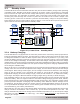
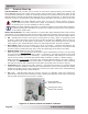
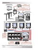
4.3.1 AC and DC Connections Simplifi ed using Magnum Panels
The AC and DC connections in a parallel system depend upon additional separate components
(highlighted in bold in the two sections below). The Magnum Panel (MP) Series of enclosures
(e.g., the AC Panel and DC Panel as shown in Figure 4-1) include all these separate components,
with most of the necessary AC and DC wiring connections already completed for you. Figures
4-2 and 4-3 are simplifi ed diagrams of the MP enclosure’s AC and DC Panels showing those
connections and components. Refer to the MP Owner’s Manual for detailed instructions on parallel
system connections.
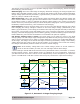
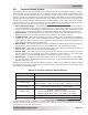
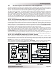
4.3.2 AC Connections Required in Parallel System
The AC input supply to the parallel system must be a 120/240 VAC split-phase system that provides
two line conductors (referred to as L1 and L2), a neutral, and ground. Each MS-PAE inverter requires
a double-pole circuit breaker rated for a maximum 30 amps per pole. Typically, the AC input
supply originates in a main distribution panel which provides the required separate AC breakers
for the AC input of each MS-PAE inverter. This main panel also includes the AC busbars to allow
the connection of the neutral and ground conductors to each inverter input.
The AC output side of a parallel system requires an electrical panel—referred to as the inverter
panel—that combines all the inverter outputs and is equipped with a large double-pole circuit
breaker rated for the total output current of the parallel system. This inverter panel must provide
the AC busbars for the neutral and ground conductors from each inverter output.
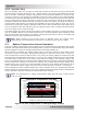
If the inverter system requires isolation from the AC source for servicing (without losing power to
the AC loads), an AC bypass should be installed between the AC input and output connections.
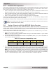
4.3.3 DC Connections Required in Parallel System
When inverters are stacked they must operate from a common battery bank. In other words,
the DC negative of one inverter must be common with the second inverter, and likewise for the
DC positive. Each inverter must be wired to the single battery bank separately and have a DC
breaker in the positive side, matched to the cable size.
All DC negatives are required to be combined on a DC busbar, and if the system requires battery
bank monitoring a full system DC shunt will need to be installed in the DC negative side.
AC
BYPASS
OFF ON
INVERTER
BUSBAR
MP SERIES
(AC PANEL)
MS-PAE INVERTERS
(1 - 4)
INOUT
AC LOADS
(Customer Connection)
AC SOURCE
(Customer Connection)
AC
BUSBARS
AC
BUSBARS
AC BREAKERS
(1 – 4)
MAS SL1 SL2 SL3
DC
BREAKERS
DC BREAKERS
(1 – 4)
MAS SL1 SL2 SL3
OPTION
MP SERIES
(DC PANEL)
MS-PAE INVERTERS
(1 - 4)
POSNEG
DC
SHUNT
DC
BUSBARS
DC
BUSBARS
DC LOADS
(Customer Connection)
DC SOURCE
(Customer Connection)
NEG POS
Figure 4-2, Simplifi ed Panel
(AC Panel)
Figure 4-3, Simplifi ed Panel
(DC Panel)