
Installation Manual


Page 18
© 2015 Sensata Technologies
Installation
2.3 AC Wiring
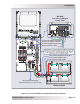
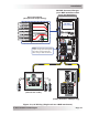
This section provides information on how to make the AC connections to the inverter using the
correct AC wire size and the corresponding overcurrent protection. Refer to Figure 2-9 for a visual
overview of the AC wiring. (Note: the MS-PAE inverter in Figure 2-9 is installed on a MMP enclosure.)
2.3.1 Pre-AC Wiring Requirements
CAUTION: Before installing any AC wiring, review the safety information and cautionary
markings at the beginning of this manual and the following guidelines.
• Always use properly rated circuit-breakers. If using an electrical sub-panel, circuit
breakers can only be moved from the main electrical panel to the sub-panel if the
breakers are also listed to be installed in the sub-panel.
• AC wiring must be no less than #10 AWG (5.3 mm
2
) gauge copper wire and be
approved for residential wiring per the NEC (THHN as an example).
• DO NOT connect the inverter’s output to an external AC power source unless used in
an AC coupled application*. Otherwise, severe damage to the inverter may occur;
and this damage is easily detected and is not covered under warranty.
* This inverter has the ability to be used in an AC coupled application, which allows
the inverter’s ouput to be connected to a grid-tie inverter’s output. The grid-tie
inverter’s output is synchronized to the inverter’s output so that the two AC outputs
can be connected together without damaging either inverter.
• The wire sizes recommended in this manual are based on the ampacities given in
Table 310.16 (in conduit) or Table 310.17 (in free air) of the NEC, ANSI/NFPA 70,
for 167°F (75°C) copper wire based on an ambient temperature of 86°F (30°C).
2.3.2 AC Wire Size and Overcurrent Protection
The AC input and output wiring must be sized to ensure the wires’ ability to safely handle the
inverter’s maximum load current. After determining the proper AC wire sizes, the inverter’s AC input
and output wires are required to be protected from short circuits and overloads by an overcurrent
protection device, and have a means to disconnect the AC circuits.
Overcurrent protection is not included in the inverter and must be provided as part of the installation.
The overcurrent protection device must be a circuit breaker or a fuse, and be properly sized and
branch circuit-rated for the wire it is protecting and the appliances being powered.
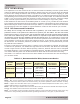
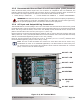
The MS-PAE Series provides a terminal block (see Figure 2-8) that allows the AC input and output
wiring to be permanently installed. This terminal block allows a service/distribution panel (main
panel) to be wired to the inverter’s input, and a dedicated panel (sub-panel) to be wired between
the inverter’s output wiring and the AC loads. These systems use the circuit breakers provided in
the panels as the overcurrent protection and the AC disconnect device.
Info: When wiring the AC input and output circuits, we highly recommend a full system
Inverter Bypass Switch. This simple item provides a convenient way to isolate the
inverter for battery maintenance, and could save hours of downtime by enabling you to
continue to power your AC loads without any re-wiring.
When in Standby mode, the full AC continuous pass-thru capacity of the MS-PAE inverter/charger
is 30 amps for each AC leg (AC HOT 1 and AC HOT 2). To obtain the 30-amp continuous pass-thru
capability, each AC HOT input to the inverter requires a 30-amp continuous duty rated double-
pole breaker
1
, which corresponds to a minimum cable size of #10 AWG
2
in conduit. If you are
using other wire sizes, refer to the appropriate electrical codes for circuit breaker requirements.
CAUTION: The inverter’s internal AC transfer relay is rated for 30 amps (each leg), the
pass-thru current must be no greater than 30 amps or damage to this relay may occur.
Note¹ – Per the NEC, if the breaker is not rated for 100% continuous duty it must be derated by
80%.
Note² – Copper wire rated with 194°F (90°C) insulation at an ambient temp of 86°F (30°C).