
Installation Manual


Page 4
© 2015 Sensata Technologies
Introduction
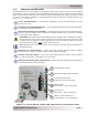
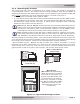
Figure 1-2, Electrical Connection Points
9
10
8
7
12
11
Positive (+)
DC Terminal
Negative (–)
DC Terminal
Mounting
Flange
DC
Equipment
Ground
Terminal
AC Entry/Exit
Connections
Intake Air Vents
(and on right side)
7
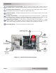
DC Equipment Ground Terminal – ties the exposed chassis of the inverter to the DC
grounding system. Accepts CU/AL conductors from #14 to #2 AWG (2.1 to 33.6 mm
2
).
8
AC Entry/Exit Connections – two 3/4” knockouts with cable-clamp strain reliefs to
accommodate and hold the AC input and output fi eld wiring.
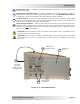
9
Intake Air Vents – ventilation openings that pull in air to keep the inverter cool for peak
performance.
10
Positive DC Terminal – a 360 degree connection point for the positive (+) cable from
the battery bank. Includes a 5/16-18 stainless Kep or Flange nut on a 5/16-18 bolt
(5/8” usable length) that holds the battery cable to the positive DC terminal.
11
Negative DC Terminal – a 360 degree connection point for the negative (–) cable
from the battery bank. Includes a 5/16-18 stainless Kep or Flange nut on a 5/16-18 bolt
(5/8” usable length) that holds the battery cable to the negative DC terminal.
12
Mounting Flange – secures the inverter to a shelf or wall.