
Installation Manual

Page 30
© 2015 Sensata Technologies
Installation
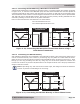
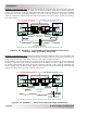
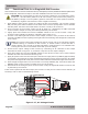
Figure 2-17, AC Voltage Checks
3
0
3030
AC Terminal Block
AC Output
120VAC
(+/- 5%)
AC Output
120VAC
(+/- 5%)
AC Output
240VAC
(+/- 5%)
Neutral to Ground
< 0.5VAC
2.8 Functional Test for a Single MS-PAE Inverter
After all electrical connections to the AC source, main panel, inverter, batteries and sub-panel have
been completed, follow these steps to test the installation and the inverter’s operation.
CAUTION: Use a multimeter to verify the correct DC voltage for your particular inverter
model (i.e., 48-volt battery bank for a 48-volt inverter), and to ensure the polarity of
the battery voltage is correct (battery positive connected to inverter positive terminal,
and battery negative connected to inverter negative terminal).
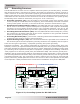
1. Apply battery power to the inverter by closing the DC circuit-breaker. The inverter remains
OFF, but the green status indicator on the front of the inverter quickly blinks once to indicate
that DC power has been connected and the inverter is ready to be turned on.
2. Prior to turning on the inverter, make sure all AC loads (i.e., appliances) are NOT connected
to the inverter’s output or to any AC outlets powered by the inverter.
3. Lightly press and release the inverter’s ON/OFF switch to turn on the inverter. Verify the
inverter’s status indicator is blinking—indicating the inverter is on.
4. Connect a ≥10-watt light bulb to the inverter output, and then verify it comes on and shines
normally. DO NOT connect anything but a light bulb until all wiring and voltages are confi rmed
to be correct.
Info: The inverter’s AC output voltage will not be correct until a >5-watt load (5 watts
is default setting) is connected to the inverter, or Search mode is turned off with a
remote display. The 10-watt or greater light bulb is used because it is a suffi cient load
to bring the inverter out of Search mode and up to full voltage.
5. Check the AC output voltage of the inverter by connecting an AC voltmeter to the output
terminals as shown in Figure 2-17, and then verify the correct output voltages.
6. Press and release the inverter’s ON/OFF switch to turn off the inverter. The inverter’s status
indicator and the connected load should go off.
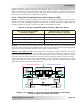
7. Apply AC power to the inverter’s AC input. After the AC input power is qualifi ed (approximately
15 seconds), the incoming AC power transfers through the inverter to the inverter’s AC output
and powers the light bulb. Verify the inverter’s status indicator and that the light bulb comes on.
8. Even though the light bulb is on, the inverter is currently disabled (off). Press and release the
ON/OFF switch on the inverter to enable (turn on) the inverter.
9. Disconnect the incoming AC power to the inverter. Verify the light bulb remains on and is now
is powered by the inverter.
If the inverter passes all the above steps, the inverter is ready for use. If the inverter fails any of
the steps, refer to the Troubleshooting section.