
Installation Manual


Page 14
© 2015 Sensata Technologies
Installation
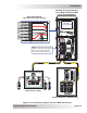
2.2.1 DC Wire Sizing
It is important to use the correct DC wire to achieve maximum effi ciency from the system and to
reduce fi re hazards associated with overheating. Always keep your wire runs as short as practical
to prevent low voltage shutdowns and to keep the DC breaker from nuisance tripping (or open
fuses) because of increased current draw. Use Table 2-1 to select the minimum DC wire size (and
corresponding overcurrent device) required based on your inverter model. The cable sizes listed in
Table 2-1 for your inverter model are required to reduce stress on the inverter, minimize voltage
drops, increase system effi ciency, and ensure the inverter’s ability to surge heavy loads.
If the distance from the inverter to the battery bank is >5 feet (1.5 m), the DC wire size needs to
be increased. Longer distances cause an increase in resistance, which affects inverter performance.
While continuing to use the overcurrent device per Table 2-1, refer then to Table 2-2 to determine
the minimum DC wire size needed for various distances—based on the model of your inverter.
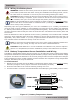
2.2.2 DC Overcurrent Protection
For safety and to comply with electrical code regulations, you must install a DC overcurrent
protection device in the positive DC cable line to protect your DC cables. This DC overcurrent
device can be a fuse or circuit breaker and must be DC rated. It must be correctly sized according
to the size of DC cables being used—which means it is required to open before the cable reaches
its maximum current carrying capability, thereby preventing a fi re. In a residential or commercial
electrical installation, the NEC requires both overcurrent protection and a disconnect switch. If a
circuit breaker is used as the overcurrent protection device, it can also be used as the required
DC disconnect. For maximum protection, install the circuit breaker (or fuse/disconnect) as near
as practical to the batteries.
If a fuse is used as an overcurrent device, a Class-T type or equivalent is required. This fuse type
is rated for DC operation, can handle the high short-circuit currents, and allows for momentary
current surges from the inverter without opening. However, because the fuse can be energized
from both directions, if it is accessible to unqualifi ed persons, the NEC requires that it be installed
in a manner that the power can be disconnected on both ends of the fuse before servicing.
Use Table 2-1 to select the DC overcurrent device based on the minimum wire size according to
your inverter model.
Table 2-1, Recommended DC Wire/Overcurrent Device
Inverter
Model
Maximum
Continuous
Current¹
NEC
Current²
Recommended
DC Wire Size
[conduit rating]³
Recommended
DC Overcur-
rent Device
DC Ground
Electrode
Wire Size
5
MS4024PAE 222 amps 278 amps
#4/0 AWG
(107.2 mm²)
[260 amps]
250 amps
4
#6 AWG
(13.3 mm²)
MS4448PAE 122 amps 153 amps
#2/0 AWG
(67.4 mm²)
[195 amps]
175 amps
#6 AWG
(13.3 mm²)
Note
1
– Maximum Continuous Current is based on continuous power rating at the lowest input voltage.
Note
2
– NEC Current is based on the Maximum Continuous Current rating with a 125% NEC derating for
sizing the overcurrent device (when not continuous duty) to prevent operation at more than 80% of rating.
Note
3
– Copper wire rated with 194°F (90°C) insulation at an ambient temperature of 86°F (30°C), with a
multiple cable fi ll factor (0.8) derating (if needed).
Note
4
– The next larger standard size overcurrent device may be used if the derated cable ampacity falls
between the standard overcurrent device sizes found in the NEC.
Note
5
– Per the NEC, the DC grounding electrode conductor can be a #6 AWG conductor if that is the only
connection to the grounding electrode and that grounding electrode is a rod, pipe, or plate electrode.