
Installation Manual


© 2015 Sensata Technologies
Page 27
Installation
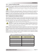
Rating of
Overcurrent Device
Minimum Size of
Copper Ground Wire
15 amps #14 AWG (2.1 mm
2
)
20 amps #12 AWG (3.3 mm
2
)
30 to 60 amps #10 AWG (5.3 mm
2
)
100 amps #8 AWG (8.4 mm
2
)
200 amps #6 AWG (13.3 mm
2
)
300 amps #4 AWG (21.1 mm
2
)
400 amps #3 AWG (26.6 mm
2
)
Table 2-4, Equipment Grounding Conductor (EGC) Sizing
2.4.2 System Bonding Jumper
The MS-PAE Series inverter/charger does not include an internal bond between the grounded
conductor (AC neutral/DC negative) and the equipment grounding terminals. This bond [System
Bonding Jumper (SBJ)] is usually done in the main distribution panel for each electrical system.
CAUTION: There should be one and only one point in each electrical system (both
AC and DC) where the grounded conductor is attached to the grounding electrode
conductor.
AC Side – The size of the system bonding jumper (SBJ) in the AC electrical system is based on
the area of the largest AC ungrounded conductor. In accordance with the NEC, use Table 2-3 to
determine the system bonding jumper size compared to the largest AC ungrounded conductor.
DC Side – The size of the system bonding jumper (SBJ) in the DC electrical system must not be
smaller than the DC grounding electrode conductor (GEC–DC) used, which is determined from the
grounding method that will be used (see Section 2.4.1).
2.4.3 Equipment Grounding Conductor
The inverter case and all other non-current-carrying exposed metal surfaces in the entire electrical
system that may be accidentally energized must be grounded. The equipment-grounding conductor
must be sized to safely carry the maximum ground-fault current likely to be imposed on it from
where a ground-fault may occur. In accordance with the NEC, use Table 2-4 to size the equipment
grounding conductors. This table requires that the equipment-grounding conductor be sized
according to the rating of the overcurrent device protecting the circuit.
CAUTION: The connections and wiring for the equipment-grounding conductor must
be continuous to allow fault currents to properly operate overcurrent devices. Where
equipment is removed, and this disconnects the bonding connection between the
grounding electrode conductor and exposed conducting surfaces, a bonding jumper
must be installed while the equipment is removed.
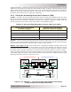
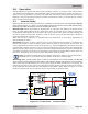
AC Side – Where the AC output from the inverter is connected to an AC load center, there should
be an equipment grounding conductor connected between the inverter case and the grounding
point in the AC load center. The AC equipment grounding conductor (EGC–AC) is sized per Table
2-4 and is connected to the inverter’s AC equipment grounding terminal shown in Figure 2-8.
DC Side – Since the currents on the DC side are higher than the AC side (5 times at 24 volts, 2.5
times at 48 volts), the equipment grounding needs are different. The DC equipment grounding
conductor (EGC–DC) is sized per Table 2-4, and is connected to the DC equipment grounding
terminal on the inverter (see Figure 1-2, Item 7).