Statement: This manual is the intellectual property of Foxconn, Inc. Although the information in this manual may be changed or modified at any time, Foxconn does not obligate itself to inform the user of these changes. Trademark: All trademarks are the property of their respective owners. Version: User’s Manual V1.1 for 560A/520A Series motherboard. Symbol description: Note: refers to important information that can help you to use motherboard better.
Declaration of conformity HON HAI PRECISION INDUSTRY COMPANY LTD 66 , CHUNG SHAN RD., TU-CHENG INDUSTRIAL DISTRICT, TAIPEI HSIEN, TAIWAN, R.O.C.
Declaration of conformity Trade Name: FOXCONN Model Name: 560A/520A Responsible Party: Address: PCE Industry Inc. 458 E. Lambert Rd. Fullerton, CA 92835 Telephone: 714-738-8868 Facsimile: 714-738-8838 Equipment Classification: Type of Product: Manufacturer: FCC Class B Subassembly Motherboard HON HAI PRECISION INDUSTRY COMPANY LTD Address: 66 , CHUNG SHAN RD., TU-CHENG INDUSTRIAL DISTRICT, TAIPEI HSIEN, TAIWAN, R.O.C.
Table of Contents Chapter 1 Main Features Specifications............................................................................................ 2 Jumpers ...................................................................................................18 Chapter 2 BIOS Description Enter BIOS Setup ................................................................................. 20 Main menu ............................................................................................ 20 1.
Attention: 1. Attach the CPU and heatsink using silica gel to ensure full contact. 2. It is suggested to select high-quality, certified fans in order to avoid damaging the motherboard and CPU due to high temperature. 3. Never turn on the computer if the CPU fan is not properly installed. 4. Ensure that the DC power supply is turned off before inserting or removing expansion cards or other peripherals, especially when you insert or remove a memory module.
1 Chapter Thank you for buying Foxconn’s 560A/520A Series motherboard. This series of motherboard is one of our new products, and offers superior performance, reliability and quality, at a reasonable price. This motherboard adopts the advanced NVIDIA nForce 560 MCP(MCP68D-GT) / nForce 520 MCP(MCP68D-S) chipset, providing a computer platform with high integration, powerful compatibility and high performance-price ratio for users.
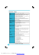
Specifications - - English Size CPU ·ATX form factor : 305mm x 193mm ·Support AMD® latest Socket AM2+ PhenomTM / AthlonTM / SempronTM series processors ·Support AMD® Socket AM2 AthlonTM 64 X2 / AthlonTM 64 / SempronTM series processors ·Supports HyperTransportTM Technology Chipset ·NVIDIA nForce 560 MCP(MCP68D-GT) / nForce 520 MCP(MCP68D-S) Hyper Transport · HT1.
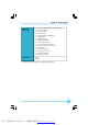
Chapter 1 Main Features Internal I/O Connectors ·2 x USB 2.0 headers(supports 4 USB 2.
第一章 主要性能 产品规格- -简体中文 尺寸 ·ATX 结构: 305mm x 193mm 中央处理器 ·支持 AMD® 最新的Socket AM2+ PhenomTM/AthlonTM/ SempronTM 系列处理器 ·支持 AMD® Socket AM2 AthlonTM 64 X2/AthlonTM 64/ SempronTM 系列处理器 · 支持 HyperTransportTM 技术 芯片组 ·NVIDIA nForce 560 MCP(MCP68D-GT)/nForce 520 MCP(MCP68D-S) 系统总线 ·HT1.
第一章 内置连接器 实用程序光盘 主要性能 ·2 个 USB 2.0 接头(提供 4 USB 2.0 接口) ·4 个 SATA 接头 ·1 个 软驱接口 ·1 个 IDE 接口 ·1 个 机箱开启侦测接头(INTR) ·1 个 CD_IN 接头 ·1 个 Speaker 接头 ·1 个 S/PDIF_OUT 接头 ·1 个 前置音频接头 ·1 个 24 针ATX 电源接口 ·1 个 4 针 ATX_12V 电源接口 ·1 个 红外线通讯接头 ·1 个 CPU 风扇接头 ·1 个 系统风扇接头 ·1 个 FAN1 风扇接头 ·前端面板接头 ·驱动程序 ·应用程序 ·规格若有任何更改,恕不另行通知 5 PDF 文件使用 "pdfFactory" 试用版本创建 www.fineprint.com.
Kapitel 1 Hauptmerkmale Technische Daten--Deutsch Größe CPU ·ATX-Formfaktor: 305 mm x 193 mm ·Unterstützt aktuellste AM2+-PhenomTM - / AthlonTM - / SempronTM -Prozessoren ·Unterstützt AMD-Prozessoren der Reihen AthlonTM 64 X2/ AthlonTM 64 / SempronTM (Sockel AM2). ·Unterstützt HyperTransport™-Technologie Chipsatz ·NVIDIA nForce 560 MCP(MCP68D-GT) / nForce 520 MCP(MCP68D-S) Hyper Transport · HT1.
Kapitel 1 Hauptmerkmale Interne I/OAnschlüsse ·2 x USB 2.0-Anschlussleisten (Unterstützung für 4 USB 2.
Capítulo 1 Principales funciones Características- -Español Tamaño · ATX factor de forma: 305mm x 193mm CPU ·Compatible con el conector más reciente de AMD, Socket AM2+ para los procesadores de la gama PhenomTM / AthlonTM / SempronTM ·Compatible con procesadores de la gama AMD Socket AM2 AthlonTM 64 X2 / AthlonTM 64 / SempronTM ·Compatible con HyperTransportTM Conjunto de chips ·NVIDIA nForce 560 MCP(MCP68D-GT) / nForce 520 MCP(MCP68D-S) Hyper Transport ·HT1.
Capítulo 1 Principales funciones Conectores ·2 x Cabeceras USB 2.0 (admite 4 puertos USB 2.
Capítulo 1 Principais características Especificações- -Portugués Tamanho ·Factor de forma ATX de 305 x 193 mm CPU ·Suporte para o mais recente socket AM2+ para processadores Phenom™/ Athlon™/SempronTM ·Suporte para socket AM2 para os processadores AthlonTM 64 X2 / AthlonTM 64 /SempronTM da AMD ·Suporta a tecnologia HyperTransportTM Chipset ·NVIDIA nForce 560 MCP(MCP68D-GT) / nForce 520 MCP(MCP68D-S) Hyper Transport ·HT1.
Capítulo 1 Principais características Conectores internos de entrada/saída ·2 x Conectores USB 2.0 (para 4 portas USB 2.
Capitolo 1 Caratteristiche principali Specifiche- -Italiano Dimensioni ·Formato ATX: 305 mm x 193 mm CPU · Supporto delle serie più recenti di processori AMD Socket AM2+ PhenomTM / AthlonTM / SempronTM ·Supporto di processori serie AthlonTM 64 X2 / AthlonTM 64 / SempronTM AMD Socket AM2 ·Supporto tecnologia HyperTransportTM Chipset ·NVIDIA nForce 560 MCP(MCP68D-GT) / nForce 520 Hyper Transport ·HT1.
Capitolo 1 Caratteristiche principali Connettori I/O ·2 x Collettori USB 2.0 (supportano 4 porte USB 2.
Глава 1 Основные характеристики Технические характеристики- -Русский ·Форм-фактор ATX размером 305 х 193 мм Размер · Поддержка новейших процессоров PhenomTM /AthlonTM Процессор / SempronTM для AMD гнезда AM2+ · Поддерживает процессоры AthlonTM 64 X2 / AthlonTM 64 /SempronTM для AMD гнезда AM2 · Поддержка технологии HyperTransportTM Набор микросхем ·NVIDIA nForce 560 MCP(MCP68D-GT) / nForce 520 MCP(MCP68D-S) Hyper Transport ·HT 1.
Глава 1 Основные характеристики Встроенные ·2 Разъемы USB 2.0 (поддержка 4 портов USB 2.
ﺍﻟﻔﺼل 1ﺍﻟﺨﺼﺎﺌﺹ ﺍﻟﺭﺌﻴﺴﻴﺔ ﺍﻟﻤﻭﺍﺼﻔﺎﺕ- -ﻟﻌﺮﺑﯿ ﺔ ﺍﻟﺤﺠﻡ Ÿﺤﺎﻭﻴﺔ ﻤﻥ ﻨﻭﻉ ATXﻤﻘﺎﺱ 305ﻤﻡ × 193ﻤﻡ ﻭﺤﺩﺓ ﺍﻟﻤﻌﺎﻟﺠﺔ ﺍﻟﻤﺭﻜﺯﻴﺔ Ÿدﻋﻢ أﺣﺪث ﺳﻠﺴﻠﺔ ﻣﻌﺎﻟﺠﺎت PhenomT M / Athlon T M / Sempron T Mﻣﻦ AMD ﺗﺪﻋﻢ ﻣﻘﺒﺲ AM2+ Ÿدﻋﻢ أﺣﺪث ﺳﻠﺴﻠﺔ ﻣﻌﺎﻟﺠﺎت Athlon T M 64 X2 / Athlon T M 64 / Sempron T Mﻣﻦ AMDاﻟﺘﻲ ﺗﺪﻋﻢ ﻣﻘﺒﺲ AM2 Ÿﺩﻋﻡ ﺘﻘﻨﻴﺔ HyperTransport T M ﺍﻟﺭﻗﺎﺌﻕ NVIDIA nFor ce 560 MCP(MCP68D- GT) / Ÿ )nFor ce 520 MCP(MCP68D-S ﺘﻘﻨﻴﺔ Hyper Transport 2000MT/
ﺍﻟﻔﺼل 1ﺍﻟﺨﺼﺎﺌﺹ ﺍﻟﺭﺌﻴﺴﻴﺔ ﻤﻨﺎﻓﺫ ﺘﻭﺼﻴل ﺍﻟﺩﺨل /ﺍﻟﺨﺭﺝ Ÿﻋﺩﺩ 2ﺃﻁﺭﺍﻑ ﺘﻭﺼﻴل ) USB 2.0ﺘﺩﻋﻡ 4ﻤﻨﺎﻓﺫ ( USB 2.
Chapter 1 Main Features Jumpers This section explains how to setup jumpers. You should read the following content carefully prior to modifying any jumper settings. Attention The jumpers on the motherboard, pin 1 can be identified by the bold silkscreen next to it. And in this manual, pin 1 is simply labeled as “1”. Clear CMOS Jumper: CLR_CMOS The CLR_CMOS jumper allows you to clear the data in CMOS. The data includes system setup information such as system password, data, time, and system setup parameters.
Chapter 2 BIOS Description 2 Chapter This chapter introduces how to change system settings through the BIOS Setup menus. Detailed descriptions of the BIOS parameters are also provided. You have to run the Setup Program when the following cases occur: 1. An error message appears on the screen during the system POST process. 2. You want to change the default CMOS settings.
Chapter 2 BIOS Description Enter BIOS Setup The BIOS is the communication bridge between hardware and software. Correctly setting up the BIOS parameters is critical to maintain optimal system performance. Power on the computer, when the following message briefly appears at the bottom of the screen during the POST (Power On Self Test), press key to enter the BIOS CMOS Setup Utility. Press TAB to show POST Screen, DEL to enter SETUP, ESC to enter Boot Menu.
Chapter 2 BIOS Description 5. Integrated Peripherals All onboard peripherals can be set up through this menu. 6. Power Management Setup Through this menu you can set up all the items of Green function features. 7. PCI/PNP Configurations The system’s PnP/PCI settings and parameters can be modified through this menu. 8. PC Health Status This menu will display the current status of your PC. 9.
Chapter 2 BIOS Description 1.1 Date/Time This item allows you to set up the desired time and date(usually as the current time and date) with / format. Day—weekday from Sun. to Sat. Month—month from 1 to 12 Date—date from 1 st to 31 st Year—year, set up by users. Use , to select a field. Use <+>or <-> to configure system time and date. 1.
Chapter 2 BIOS Description All Errors No Errors All, But Keyboard All, But Diskette All, But Disk/Key Whenever the BIOS detects a nonfatal error, the system will stop and you will be prompted. The system boot will not stop for any errors that may be detected. The system boot will not stop for a keyboard error; but it will stop for all other errors. The system boot will not stop for a diskette error; but it will stop for all other errors.
Chapter 2 BIOS Description 2.6 K8<->NB HT Width Allows you to set the bandwidth of the link’s transmitter of K8<->NB. 2.7 DRAM Configuration DRAM Configuration Menu Timing Mode This item is used to set DRAM timing mode. The available values setting are: Auto, MaxMemClk. Memory CLK value or Limit W hen “Timing Mode” set to “MaxMemClk”, you can select the frequency of memory. DDRII Timing Item This item allows you manually adjust DDRII timing. W hen enabled, you can set some parameters of DDRII timing.
Chapter 2 BIOS Description (Trc)Row Cycle Time Allows you to set the minimum time interval between successive active commands to the same bank. (Trcd) RAS to CAS R/W Delay Allows you to set the number of clock cycles taken between the issuing of the active command and the read/write command. (Trrd) RAS to RAS Delay Allows you to set the minimum time interval between successive active commands to the different banks.
Chapter 2 BIOS Description 3.Advanced BIOS Features Advanced BIOS Features Menu 3.1 Removable Device Priority This option is used to select the priority for Removable Device, e.g. floppy. 3.2 Hard Disk Boot Priority This option is used to select the priority for HDD startup. After pressing , you can select the HDD using the Up / Down arrow keys, and change the HDD priority using / or <+> / <->; you can exit this menu by pressing . 3.
Chapter 2 BIOS Description 3.8 Security Option W hen it is set to “Setup”, a password is required to enter the CMOS Setup screen; W hen it is set to “System”, a password is required not only to enter CMOS Setup, but also to start up your PC. 3.9 Full Screen LOGO Show This option allows you to enable or disable the full screen logo. 3.10 Small Logo (EPA) Show This item allows you to enable or disable the EPA logo. 4.
Chapter 2 BIOS Description 5.2 RAID Config This sub-menu allows you to set RAID configurations. 5.3 Onboard Device This sub-menu allows you to set the configuration of onboard devices. 5.4 SuperIO Device This sub-menu is used for the configuration of I/O devices, such as serial port, parallel port and so on. 5.5 USB Device Setting This sub-menu is used to set the parameters of USB devices. 6.Power Management Setup Power Management Setup Menu 6.
Chapter 2 BIOS Description when “Delay 4 sec”, the power will be off after the power button is pressed for more than 4 seconds. 6.4 PWRON After PWR-Fail This item is used to set what action the PC will take with the power supply when it resumes after a sudden power failure. The available options are: Off (remain in turn off status), On (auto power on) and Former-Sts (resume with the previ-ous status). 6.5 Resume by PCI card This item is used to set the Resume by PCI card. 6.
Chapter 2 BIOS Description 7.PnP/PCI Configurations PnP/PCI Configurations Menu 7.1 Resources Controlled By This option is used to set whether the system is permitted to automatically distribute IRQ DMA and I/O addresses when each time that the machine is turned on. 7.2 IRQ Resources Press the key, then manually set IRQ resources. 7.3 PCI/VGA Palette Snoop If you use a non-standard VGA card, use this option to solve graphic acceleration card or MPEG audio card problems (e.g.
Chapter 2 BIOS Description 8.1 Case Open Warning Enable or disable the chassis open status feature. 8.2 CPU Smart Fan Control Enable or disable CPU Smart Fan Control. 8.3 Smart Fan1 Temp1 Value Allows you to set the initial temperature of smart fan1. When the temperature achieve the value and “CPU Smart Fan Control” is enabled, the smart fan will be turn on. 8.4 Smart Fan1 PWM Start Duty Allows you to set the initial PW M value of smart fan1. 8.
Chapter 2 BIOS Description Enter Password: Enter your password, not exceeding 8 characters, then press . The password you enter will replace any previous password. W hen prompted, key in the new password and press . If you do not want to set a password, just press when prompted to enter a password, and in the screen the following message will appear. If no password is keyed in, any user can enter the system and view/modify the CMOS settings.
Chapter 4 Driver CD Introduction Chapter 3 This chapter will introduce how to use attached software. This chapter provides the following information: v v v v FOX ONE FOX LiveUpdate FOX LOGO FOX DMI 33 PDF 文件使用 "pdfFactory" 试用版本创建 www.fineprint.com.
Chapter 3 Directions for Bundled Software FOX ONE FOX ONE is a powerful utility for easily modifying system settings. It also allows users to monitor various temperature values, voltage values, frequency and fan speed at any time. Supported Operating Systems: -W indows 2000 -Windows XP (32-bit and 64-bit) -W indows 2003 (32-bit and 64-bit) -W indows Vista (32-bit and 64-bit) Using FOX ONE: The very first time you run FOX ONE, F.I.S.
Chapter3 Directions for Bundled Software Alert Lamp When the system is in healthy status, the alert lamp color is green. When in abnormal status, the color will turn red. Switch Button Click this button, it will simplify the window to HW monitor information bar as the below figure shows. The bar could help you to monitor whether your system is in the healthy status or not at any time.
Chapter 3 Directions for Bundled Software 2. CPU Page - CPU Control This page is used to select and run the CPU frequency to determine the current performance level of the system. You can adjust the CPU frequency manually or select “Auto Overclock”. Besides, it also provides “FOX Intelligent Stepping”, but this function is optional. Go to CPU page Auto Overclocking Adjust manually Select the different benchmarks Resume default setting Apply the changes 3. Freq.
Chapter3 Directions for Bundled Software 4. Limit Setting page This page includes five different sections. “CPU Temp.” and “Sys. Temp.” will help you to set high limit temperature. “CPU Fan”, “Sys. Fan” and “FAN1 fan” are used to set low limit rpm. All of them have alert function.
Chapter 3 Directions for Bundled Software Go to Fan page Enable or disable smart fan function Set fan speed by dragging the lever Resume default setting Apply the changes FOX LiveUpdate FOX LiveUpdate is a useful utility to backup and update the system BIOS online or locally. Drivers and utilities aslo can be updated online. Supported Operating Systems: -W indows 2000 -Windows XP (32-bit and 64-bit) -W indows 2003 (32-bit and 64-bit) -W indows Vista (32-bit and 64-bit) Using FOX LiveUpdate: 1.
Chapter3 Directions for Bundled Software 2. Online Update This function enables you to update your system BIOS, Drivers, Utilities and all of them from Internet. Click “start”, it will search for the new BIOS, Drivers and Utilities from Internet. Then follow the request to finish the update operation. Current information Click here Search for new BIOS, Drivers and Utilities from Internet 3. Configure “Option” provides “auto search options”, “auto search Fox LiveUpdate” and “version filter”.
Chapter 3 Directions for Bundled Software 4. About & Help This page shows some information about FOX LiveUpdate. Information about FOX LiveUpdate Click here FOX LOGO FOX LOGO is a simple and useful utility to backup, change and delete the boot Logo. The boot Logo is the image that appears on screen during the Power-On Self-Tests (POST).
Chapter3 Directions for Bundled Software FOX DMI FOX DMI is a full DMI information viewer, and it supports three kinds of DMI Data format :Report, Data Fields and memory Dump. Supported Operating Systems: -W indows 2000 -Windows XP (32-bit and 64-bit) -W indows 2003 (32-bit and 64-bit) -W indows Vista (32-bit and 64-bit) Using FOX DMI: Please operate this utility as the comments show. Click here to select the DMI Data format Click here to select the type 41 PDF 文件使用 "pdfFactory" 试用版本创建 www.fineprint.