Statement: This manual is the intellectual property of Foxconn, Inc. Although the information in this manual may be changed or modified at any time, Foxconn does not obligate itself to inform the user of these changes. Trademark: All trademarks are the property of their respective owners. Intel® and Pentium® are registered trademarks of Intel Corporation. PS/2 and OS/2 is the registered trademarks of IBM, Inc. Windows® 95/98/2000/NT/XP is the registered trademark of Microsoft.
Item Checklist: Thank for your purchasing Foxconn’s 661M03 series motherboard. Please check the package; if there are missing or damaged items, contact your distributor as soon as possible. 661M03 series motherboard (x1) Foxconn Utility CD (x1) User’s Manual (x1) IDE Ribbon cable (x1) FDD Ribbon cable (x1) I/O Shield (x1) SPDIF Cable (x1) (optional) USB 2.
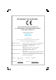
Declaration of conformity HON HAI PRECISION INDUSTRY COMPANY LTD 66 , CHUNG SHAN RD., TU-CHENG INDUSTRIAL DISTRICT, TAIPEI HSIEN, TAIWAN, R.O.C.
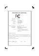
Declaration of conformity Trade Name: Model Name: Responsible Party: Foxconn 661M03 PCE Industry Inc. Address: 458 E. Lambert Rd. Fullerton, CA 92835 714-738-8868 714-738-8838 Telephone: Facsimile: Equipment Classification: Type of Product: Manufacturer: FCC Class B Subassembly Motherboard HON HAI PRECISION INDUSTRY COMPANY LTD 66 , CHUNG SHAN RD., TU-CHENG INDUSTRIAL DISTRICT, TAIPEI HSIEN, TAIWAN, R.O.C. Address: Supplementary Information: This device complies with Part 15 of the FCC Rules.
Table of Contents Chapter 1 Product Introduction Main Features .............................................................................................. 2 Motherboard Layout .................................................................................... 5 Chapter 2 Installation Instructions CPU ............................................................................................................ Memory ...................................................................................
Table of Contents Chapter 4 Driver CD Introduction Utility CD content ........................................................................................ Start to install drivers ................................................................................. Install IDE Driver ......................................................................................... Install AGP Driver ....................................................................................... Install VGA Driver ........
Warning: 1. Attach the CPU and heatsink using silica gel to ensure full contact. 2. It is suggested to select high-quality, certified fans in order to avoid damage to the motherboard and CPU due to high temperatures. 3. Never turn on the machine if the CPU fan is not properly installed. 4. Ensure that the DC power supply is turned off before inserting or removing expansion cards or other peripherals, especially when you insert or remove a memory module.
1 Chapter Thank you for your buying Foxconn’s 661M03 series motherboard. This series of motherboard is one of our new products and offers superior performance, reliability and quality, at a reasonable price. This motherboard adopts the advanced SiS 661FX+ 963/963L chipset, providing users a computer platform with a high integration-compatibilityperformance price ratio.
Chapter 1 Product Introduction Main Features Size mATX form factor of 9.6”x 8.
Chapter 1 Product Introduction Onboard 1394 (optional) Supports hot plug With rate of transmission up to 400Mbps Self-configured addressing Can connect with 2 independent 1394 units synchronously at most, such as HDD, CD-ROM Onboard LAN Supports 10/100Mbit/sec Ethernet LAN interface built-in on board Onboard I/O Two high-speed 16550 compatible UARTs (COM1/COM2) with 16 byte send/ receive FIFO One infrared interface (optional) One parallel port supporting SPP/EPP/ECP mode Onboard Graphics Supports integrat
Chapter 1 Product Introduction Green Function Supports ACPI (Advanced Configuration and Power Interface) Supports five system modes—S0 (normal), S1 (power on suspend), S3 (suspend to RAM), S4 (suspend to disk – depends on OS) and S5 (soft-off) Advanced Features PCI 2.
Chapter 1 Product Introduction Motherboard Layout 16 15 1 14 2 13 3 4 5 12 6 7 11 10 9 8 Note: The above motherboard layout is provided for reference only; please refer to the physical motherboard.
Chapter 1 Product Introduction 1 1394 PHY (optional) The RTL8801B is IEEE 1394a 100/200/400 Mbps 2-Port Cable Transceiver/ Arbiter (PHY) Chip. Provides two fully compliant cable ports at 100/200/400 Mbps. 2 ATX 12V connector This power connector connects the 4-pin 12V plug from the ATX 12V power supply. 3 AGP slot This Accelerated Graphics Port (AGP) slot supports 1.5V AGP 8X/4X mode graphics cards for 3D graphical applications.
Chapter 1 Product Introduction 9 Floppy disk connector This connector accommodates the provided ribbon cable for the floppy disk drive. One side of the connector is slotted to prevent incorrect insertion of the floppy disk cable. 10 IDE connectors These dual-channel bus master IDE connectors support Ultra DMA 133/ 100/66/33 devices. Both the primary (blue) and secondary (white) connectors are slotted to prevent incorrect insertion of the IDE ribbon cable.
Chapter 2 Chapter Installation Instructions 2 This chapter introduces the hardware installation process, including the installation of the CPU and memory. It also addresses the connection of your power supply, use of the rear panel connectors, connection of hard drive and floppy drive data cables, and setting up various other feature of the motherboard. Caution should be exercised during the installation process.
Chapter 2 Installation Instructions Notes: Take note of the following precautions before you install components or change settings. 1. Use a grounded wrist strap or touch a safely grounded object, such as an attached power supply, before handling components to avoid damaging them due to static electricity. 2. Unplug the power cord before opening your chassis or touching any component. 3. Hold components by their edges to avoid touching any exposed integrated circuits (ICs). 4.
Chapter 2 Installation Instructions CPU This motherboard accepts Intel socket 478 processors (CPUs) with a front side bus (FSB) of 400/533/800 MHz processors with Hyper-Threading technology are supported. Warning : The CPU pins must be properly aligned with the holes in the socket, otherwise the CPU may be damaged. Installation of CPU Follow these steps to install a CPU. 90° 1. Unlock the socket by pressing the lever sideways, then lift it up to a 900 Gap in the base angle. 2.
Chapter 2 Installation Instructions Installation of CPU Fan New technology allows processors to run at higher and higher frequencies. To avoid problems arising from high-speed operation, for example, overheating, you need to install the proper fan. The following procedures are provided for reference only, please refer to your CPU fan user guide to install it. 1. Locate the CPU retention mechanism 2. base (surrounds the CPU socket). If required, apply a light coating of silica gel to the top of the CPU.
Chapter 2 Installation Instructions Attention: 1.Position the fan with the retention mechanism on top of the heatsink. Align and snap the four hooks of the retention mechanism to the holes on each corner of the module base. 2. Make sure that the fan and retention mechanism assembly perfectly fits the heatsink and module base, otherwise you cannot snap the hooks into the holes.
Chapter 2 Installation Instructions Attention: 1. Push down the locks on the retention mechanism to secure the heatsink and fan to the module base. 2. When secured, the retention locks should point to opposite directions. CPU Qualified Vendor List The following table lists the CPU modules that have been tested and qualified for use with this motherboard. Vendor Type FSB Frequence Intel Pentium (Northwood) 400 MHz 2.0GHz, 2.5GHz Intel Pentium (Northwood) 533 MHz 2.4GHz, 2.66GHz, 2.8GHz, 3.
Chapter 2 Installation Instructions Memory This motherboard includes two, 184-pin, dual in-line memory module (DIMM) sockets. You can install corresponding PC 3200 (DDR400), PC 2700 (DDR333), or PC 2100 (DDR266) memory modules. You must install at least one memory module to ensure normal operation. If you install two modules, they must be the same speed. Mixing memory modules from differen t manufacturers is not recommended. DIMM1 DIMM2 Installation of DDR Memory 1.
Chapter 2 Installation Instructions Warning : Be sure to unplug the AC power supply before adding or removing expansion cards or other system peripherals, especially the memory devices, otherwise your motherboard or the system memory might be seriously damaged. Memory Qualified Vendor List The following table lists the Memory modules that have been tested and qualified for use with this motherboard.
Chapter 2 Vender HY Samsung Samsung Type PC3200 (DDR 400) PC2100 (DDR 266) PC3200 (DDR 400) Installation Instructions Size 256M,512M 128M, 256M 512M Note: Make sure to use only the tested and qualified DDR DIMMS listed above. Other DDR DIMMs manufactured by other vendors may not be suitable for this motherboard.
Chapter 2 Installation Instructions Power Supply This motherboard uses an ATX power supply. In order to avoid damaging any devices, make sure that they have been installed properly prior to connecting the power supply. 20-pin ATX power connector: PWR1 PWR1 is the ATX power supply connector. Make sure that the power supply cable and pins are properly aligned with the connector on the motherboard. Firmly plug the power supply cable into the connector and make sure it is secure.
Chapter 2 Installation Instructions Rear Panel Connectors This motherboard provides the ports as below: 4 Parallel Port (Printer Port) 7 1394 Port (optional) 8 LAN connector Line-in jack 1 PS/2 Mouse Connector Line-out jack 9 Microphone 2 PS/2 Keyboard Connector jack 3 Serial Port 5 VGA Connector 6 USB 2.0 Port x 4 (COM1) PS/2 Mouse Connector This green 6-pin connector is for a PS/2 Mouse. 1 PS/2 Keyboard Connector This purple 6-pin connector is for a PS/2 keyboard.
Chapter 2 Installation Instructions LAN connector This port allows connection to a Local Area Network (LAN) through a network hub. 8 Line-in jack, Line-out jack, Microphone jack When using a two-channel sound source, the Line-out jack is used to connect to speakers or headphones; the Line-in port connects to an external CD player, tape player or other audio device. The Microphone jack is used to connect to the microphone.
Chapter 2 Installation Instructions Other Connectors This motherboard includes connectors for FDD, IDE HDD, USB, CPU/system fan, and others. FDD Connector This motherboard includes a standard FDD connector, supporting 360K, 720K, 1.2M, 1.44M, and 2.88M FDDs. 1 FDD connector HDD connectors: IDE1 & IDE2 This connectors supports the provided UltraDMA 133/100/66 IDE hard disk ribbon cable.
Chapter 2 Installation Instructions IDE 2 1 IDE 1 Front Panel Connector: F_P1 This motherboard includes one connector for connecting the front panel switch and LED indicators. HD-LED 1 + - + - RESET PWR-LED PWR-SW NC F_P1 Hard Disk LED Connector (HD-LED) The connector connects to the case’s IDE indicator LED indicating the activity status of IDE hard disk.
Chapter 2 Installation Instructions IrDA Header: IR (optional) This connector supports wireless transmitting and receiving device. Before using this function, configure the settings of IR Address, IR Mode and IR IRQ from the “INTEGRATED PERIPHERALS” section of the CMOS SETUP.
Chapter 2 Installation Instructions Fan Connectors: CPU_FAN, FAN1 The speed of CPU_FAN and FAN1 can be detected and viewed in “PC Health Status” section of the CMOS SETUP. These fans will be automatically turned off after the system enters suspend mode. 1 SENSE +12V GND CPU_FAN GND +12V SENSE 1 FAN1 Audio Connectors: CD_IN CD_IN is Sony standard CD audio connector, it can be connected to a CD-ROM drive through a CD audio cable.
Chapter 2 Installation Instructions 1394 Header: F_1394 (optional) The 1394 expansion cable can be connected to either the front (provided that the front panel of your chassis is equipped with the appropriate interface) or real panel of the chassis. Empty B + A+ VCC GND 1 VCC GND GND B- A- F_1394 Wake-Up On LAN: WOL Through the Wake-Up On LAN function, a wake event occurring from the network can wake up the system.
Chapter 2 Installation Instructions Audio Interface: F_AUDIO The audio interface provides two kinds of audio output choices: the Front Audio, the Rear Audio. Their priority is sequenced from high to low (Front Audio to Rear Audio). If headphones are plugged into the front panel of the chassis (using the Front Audio), then the Speaker Out (Rear Audio) on the rear panel will not work.
Chapter 2 Installation Instructions Expension Slots This motherboard includes three 32-bit Master PCI bus slots, one AGP slot and one CNR slot (optional). PCI Slots The expansion cards can be installed in the three PCI slots. When you install or take out such cards, you must make sure that the power plug has been pulled out. Please read carefully the instructions provided for such cards, and install and set the necessary hardware and software for such cards, such as the jumper or BIOS setup.
Chapter 2 Installation Instructions Warning: The motherboard may be damaged if a 3.3V AGP card is used. Make sure that your AGP card is 1.5V specification. Note the notches on the card golden fingers to ensure that they fit the AGP slot on your motherboard. Installing an expansion card 1. Before installing the expansion card, read carefully the documentation that came with it and make the necessary hardware settings for the card. 2.
Chapter 2 Vender Installation Instructions Type Video Memory WinFast A340 TDH 8X 128MB Gigabyte GA-GF1280 GeForce 2 MX 32MB UNIKA 7917 Geforce4 MX440 64MB Gigabyte GV-R9600 8X 128MB WinFast S650 GeForce 3 Ti500 4X 64MB ELSA ELSA GLADIAC 518 8X 64MB ATI ATI 7000 VE 4X 64MB Note: Make sure to use only the tested and qualified AGP card listed above. Other AGP card manufactured by other vendors may not be suitable for this Motherboard.
Chapter 2 Installation Instructions Jumpers The users can change the jumper settings on this motherboard if needed. This section explains how to use the various functions of this motherboard by changing the jumper settings. Users should read the following contents carefully prior to modifying any jumper settings. Description of Jumpers 1. For the jumpers on this motherboard, pin 1 can be identified by the silkscreen printed “ ” next to it. However, in this manual, pin 1 is simply labeled as “1”. 2.
Chapter 2 Installation Instructions Warning: 1. Disconnect the power cable before adjusting the jumper settings. 2. Do not clear the CMOS while the system is turned on. BIOS-Protection Jumper: FWH_EN The motherboard BIOS is inside the FWH. If the jumper FWH_EN is set as disable (Pin2 & Pin3), the system BIOS is protected from being attacked by a serious virus, such as the CIH virus. You will be unable to flash the BIOS to the motherboard when the system BIOS is protected.
Chapter 2 Installation Instructions Starting up for the first time 1. After making all the connections, replace the system case cover. 2. Be sure that all switches are off. 3. Turn on the devices in the following order. a. Monitor b. External SCSI devices (starting with the last device on the chain) c. System power 4. After applying power Led on the system front panel case lights up. For ATX power supplies, the system LED lights up when you press the ATX power switch.
Chapter 3 Chapter BIOS Description 3 This chapter tells how to change system settings through the BIOS Setup menus. Detailed descriptions of the BIOS parameters are also provided. You have to run the Setup Program when the following cases occur: 1. An error message appears on the screen during the system POST process. 2. You want to change the default CMOS settings.
Chapter 3 BIOS Description Enter BIOS Setup The BIOS is the communication bridge between hardware and software, correctly setting up the BIOS parameters is critical to maintain optimal system performance. Power on the computer, when the following message briefly appears at the bottom of the screen during the POST (Power On Self Test), press key to enter the AWARD BIOS CMOS Setup Utility. Press TAB to show POST screen, DEL to enter SETUP.
Chapter 3 BIOS Description Advanced BIOS Features The advanced system features can be set up through this menu. Advanced Chipset Features The values for the chipset can be changed through this menu, and the system performance can be optimized. Integrated Peripherals All onboard peripherals can be set up through this menu. Power Management Setup All the items of Green function features can be set up through this menu.
Chapter 3 BIOS Description Standard CMOS Features This sub-menu is used to set up the standard CMOS features, such as the date, time, HDD model and so on. Use the arrow keys select the item to set up, and then use the or keys to choose the setting values. Standard CMOS Features Menu Date This option allows you to set the desired date (usually as the current day) with the format. Day—weekday from Sun. to Sat., defined by BIOS (read-only). Month—month from Jan.
Chapter 3 BIOS Description Award (Phoenix) BIOS can support 3 HDD modes: CHS, LBA and Large or Auto mode. CHS For HDD<528MB LBA For HDD>528MB & supporting LBA (Logical Block Addressing) Large For HDD>528MB but not supporting LBA Auto Recommended mode Drive A/B This option allows you to select the kind of FDD to be installed, including “None”, [360K, 5.25 in], [1.2M, 5.25 in], [720K, 3.5 in], [1.44M, 3.5 in] and [2.88 M, 3.5 in].
Chapter 3 BIOS Description Memory This is a Display-Only Category, determined by POST (Power On Self Test) of the BIOS. Base Memory Extended Memory Total Memory The BIOS POST will determine the amount of base (or conventional) memory installed in the system. The BIOS determines how much extended memory is present during the POST. Total memory of the system.
Chapter 3 BIOS Description BIOS Features BIOS Features Menu [SuperBoot] SuperBoot (Default: Disabled) SuperBoot allows system-relevant information to be stored in CMOS upon the first normal start-up of your PC, and the relevant parameters will be restored to help the system start up more quickly on each subsequent start-up. The available setting values are: Disabled and Enabled.
Chapter 3 BIOS Description Advanced BIOS Features Advanced BIOS Features Menu CPU Feature Press enter to set the items of CPU feature. Please refer to page 42. Virus warning (Default: Disabled) Allows you to choose the VIRUS warning feature for IDE hard disk boot sector protection. If this function is enabled and someone attempt to write data into this area, BIOS will show a warning message on screen and an alarm will beep. The available setting values are: Disabled and Enabled.
Chapter 3 BIOS Description Quick Power On Self Test (Default: Enabled) Enable this option to shorten the power on testing (POST) and have your system start up faster. The available setting values are: Disabled and Enabled. First/Second/Third Boot Device (Default: Floppy/HDD- 0/CDROM) This option allows you to set the boot device’s sequence. The available setting values are: Floppy, LS120, HDD-0, SCSI, CDROM, HDD-1, HDD-2, HDD-3, ZIP100, USB-FDD, USB-ZIP, USB-CDROM, USB-HDD, LAN and Disabled.
Chapter 3 BIOS Description Typematic Delay (Msec) (Default: 250) Use this option to define how many milliseconds must elapse before a helddown key beings generating repeat characters. Security Option (Default: Setup) When it is set to “Setup”, a password is required to enter the CMOS Setup screen; When it is set to “System”, a password is required not only to enter CMOS Setup, but also to start up your PC. APIC Mode (Default: Enabled) This option is used to enable or disable APIC mode.
Chapter 3 BIOS Description CPU Feature Menu Thermal Management (Default: Thermal Monitor 1) This option is used to manage Prescott CPU thermal. Note: This function will not be displayed until a Prescott CPU has been installed. TM2 Bus Ratio (Default: 0 X) Represents the frequency bus ratio of the throttled performance state that will be initiated when the on-diesensor gose from not hot to hot. TM2 Bus VID (Default: 0.
Chapter 3 BIOS Description Advanced Chipset Features Advanced Chipset Features Menu DRAM Clock/Timing Control Press enter to set the items about DDR RAM. Please refer to page 44. AGP & P2P Bridge Control Press enter to set the items about AGP. Please refer to page 45. OnChip AGP Control Press enter to set the items about onchip AGP. Please refer to page 46. System BIOS Cacheable (Default: Enabled) Select “Enabled” to allow caching of the system BIOS which may improve performance.
Chapter 3 BIOS Description DRAM Clock/Timing Control Menu Performance Mode (Default: Disabled) This option is used to disable or enable performance mode. DRAM Timing control (Default: By SPD) This option determines DRAM timing using SPD or manual configuration. Only set as manual, the following 4 items can be updated. DRAM CAS Latency (Default: 2.5T) This option determines CAS Latency. The available setting values are: 2T, 2.5T, 3T.
Chapter 3 BIOS Description AGP & P2P Bridge Control Menu AGP Aperture Size (Default: 64 MB) This option defines the size of the aperture if you use an AGP graphics adapter. The aperture is a portion of the PCI memory address range dedicated for graphic memory address space. Note: This function does not work when Onboard VGA is used. Graphic Window WR Combin (Default: Disabled) This option is used to disable or enable Graphic Window Write Combin mode.
Chapter 3 BIOS Description OnChip AGP Control Menu VGA Share Memory Size (Default: 32 MB) This option is used to set the onboard VGA share memory size. The available setting are 16MB, 32MB, 64MB, 128MB. Graphics Engin Clock (Default: 133 MHz) This option is used to set onchip AGP graphics engin clock. The available setting are 100 MHz, 133MHZ, 166MHZ, 200MHz.
Chapter 3 BIOS Description Integrated Peripherals Integrated Peripherals Menu SIS Onchip IDE Device Press enter to set onchip IDE device. Please refer to page 48. SIS Onchip PCI Device Press enter to set onchip PCI device. Please refer to page 49. Onboard SuperIO Device Press enter to set Onboard SuperIO device. Please refer to page 50. IDE HDD Block Mode (Default: Enabled) This option is used to set whether the IDE HDD Block Mode is allowed. The available setting values are: Disabled and Enabled.
Chapter 3 BIOS Description Audio Access Interface (Default: EDB Bus) This option is used to set audio Access Interface. The available setting values are: PCI Bus and EDB Bus. SIS OnChip IDE Device Menu Internal PCI/IDE (Default: Both) This option is used to set the ports of onboard IDE. The available setting values are: Disabled, Primary, Secondary and Both.
Chapter 3 BIOS Description SIS OnChip PCI Device Menu SIS USB Controller (Default: Enabled) This option is used to enable or disable SIS USB controller. USB Ports Number (Default: 6 ports) This option is used to select the USB ports number. USB 2.0 Supports (Default: Enabled) This option is used to enable or disable USB 2.0. USB Keyboard Support (Default: Enabled) This option is used to enable or disable USB keyboard under legacy OS.
Chapter 3 BIOS Description Onboard SuperIO Device Menu Onboard FDC Controller (Default: Enabled) This option is used to set whether the Onboard FDC Controller is enabled. The available setting values are: Disabled and Enabled. Onboard Serial Port1/2 (Default: 3F8/IRQ4 / 2F8/IRQ3) This option is used to assign the I/O address and interrupt request (IRQ) for the onboard serial port 1/2. Note: Do not try to set the same values for serial ports 1 and 2.
Chapter 3 BIOS Description Power Management Setup Power Management Setup Menu ACPI function (Default: Enabled) ACPI stands for “Advanced Configuration and Power Interface”. ACPI is a standard that defines power and configuration management interfaces between an operating system and the BIOS. In other words, it is a standard that describes how computer components work together to manage system hardware.
Chapter 3 BIOS Description Video Off Option (Default: Susp, Stby - > off) This option is used to set video off option. The setting values are Always On, Suspend -> off, Susp,Stby - > off, All Modes -> off. Video Off Method (Default: DPMS Supported) This option is used to define the video off method. “Blank Screen” mode means that after the computer enters power saving mode, only the monitor will close, however, the vertical and horizontal scanning movement of the screen continues.
Chapter 3 BIOS Description PM Wake Up Events Menu IRQ [3-7,9-15], NMI (Default: Enabled) This option is used to enable or disable IRQ[3-7,9-15], NMI. IRQ 8 Break Suspend (Default: Disabled) This option is used to enable or disable IRQ8 break suspend. RING Power Up Control (Default: Enabled) If this option is enable, it allows the system to resume from a software power down or power saving mode whenever there is an incoming call to an installed fax/modem.
Chapter 3 BIOS Description Month Alarm This option is used to set the timing for the start-up month. The setting values contain 0 - 12 and NA. Day of Month Alarm This option is used to set the timing for the start-up day of the month. The setting values contain 0 - 31. Time (hh:mm:ss) Alarm This option is used to set the timing for the start-up time. The setting values contain hh:0 – 23; mm:0 – 59; ss:0 – 59.
Chapter 3 BIOS Description PnP/PCI Configurations PnP/PCI Configurations Menu Reset Configuration Data (Default: Disabled) This option is used to set whether the system is permitted to automatically distribute IRQ DMA and I/O addresses when each time that the machine is turned on. The setting values are Disabled and Enabled. Resources Controlled By (Default: Auto(ESCD)) This option is used to define the system resource control scheme.
Chapter 3 BIOS Description PC Health Status PC Health Status Menu Vccp, +3.3v, +5v, +12v The current voltages will be automatically detected by the system. CPU Temp The current CPU temperature will be automatically detected by the system. System Temp1 The system temperature1 will be automatically detected by the system. System Temp2 The system temperature2 will be automatically detected by the system. CPU FAN Speed The CPU fan speed will be automatically detected by the system.
Chapter 3 BIOS Description Frequency/Voltage Control Frequency/Voltage Control Menu CPU Clock Ratio (Default: based on CPU specifications) This option is used to set the ratio of an unlocked CPU. Using different CPU, the setting values are different. Note: this option is invisible for locking frequency CPU. Auto Detect DIMM/PCI Clk (Default: Enabled) This option is used to set whether the clock of an unused PCI/DIMM slot will be disabled to reduce electromagnetic interference.
Chapter 3 BIOS Description Load Fail-Safe Defaults Press to select this option. A dialogue box will pop up that allows you to load the default BIOS settings. Select and then press to load the defaults. Select and press to exit without loading. The defaults set by BIOS set the basic system functions in order to ensure system stability. But if your computer cannot POST properly, you should load the fail-safe defaults to restore the original settings.
Chapter 3 BIOS Description Under the menu “Advanced BIOS Features Setup”, if you select “System” from the Security Option, you will be prompted to enter a password once the system is started or whenever you want to enter the CMOS setting program. If the incorrect password is entered, you will not be permitted to continue. Under the menu “Advanced BIOS Features Setup”, if you select “Setup” from the Security Option, you will be prompted to enter a password only when you enter the CMOS setting program.
Chapter 4 Chapter Driver CD Introduction 4 The utility CD that came with the motherboard contains useful software and several utility drivers that enhance the motherboard features. This chapter includes the following information: 60 Utility CD content Start to install drivers Install IDE Driver Install AGP Driver Install VGA Driver Install Direct X Install USB2.
Chapter 4 Driver CD Introduction Utility CD content This motherboard comes with one Utility CD. To begin using the CD, simply insert the CD into your CD-ROM drive. The CD will automatically displays the main menu screen. 1. Install Driver Using this choice, you can install all the drivers for your motherboard. You should install the drivers in order and you need to restart your computer after the drivers all installed. A. IDE Driver B. AGP Driver C. VGA Driver D. Direct X E. USB 2.0 Driver F.
Chapter 4 Driver CD Introduction Start to Install divers Select , and click to enter the install driver screen. You can select the driver that you want to install and begin the setup steps. Note: The following setup steps are based on Windows XP environment. There may be some differences with other operating systems. Install IDE Driver Click from the main menu and enter the install driver menu (as shown in fig. 1). Click to start the installation.
Chapter 4 Driver CD Introduction Install AGP Driver Click from the main menu and enter the install driver menu (as shown in fig. 1). Click to start the installation. Click here Click here 2 1 Select this option Click here Click here 4 3 Install VGA Driver Click from the main menu and enter the install driver menu (as shown in fig. 1). Click to start the installation.
Chapter 4 Driver CD Introduction Click here Click here 4 3 Click here Click here 6 5 Install DirectX Click from the main menu and enter the install driver menu (as shown in fig. 1). Click to start the installation.
Chapter 4 Driver CD Introduction Click here Click here 4 3 Install USB 2.0 Driver Click from the main menu and enter the install driver menu (as shown in fig. 1). Click to open the USB 2.0 setup guide. Please read the guide carefully and select the relevant installation method. If you want to know further information, please visit our website: www.foxconnchannel.com.
Chapter 4 Driver CD Introduction Click here Click here 2 1 Click here 3 Attaching Speakers To perform multichannel audio operation, connect multiple speakers to the system. You should connect the same number of speakers as the audio channels you will select in the software utility. 2-Channel Analog Audio Output The audio connectors on the rear panel already provide 2-Channel analog audio output.
Chapter 4 Driver CD Introduction 2-Channel Analog Audio Output Line-in Line-out (Front channels) Microphone Description: Line-out, Line-in and Microphone functions all exist under 2-Channel configuration. 4-Channel Analog Audio Output Line-out (Rear channels) Line-out (Front channels) Microphone Description: Line-in is converted to Line-out under the 4-Channel configuration.
Chapter 4 Driver CD Introduction Digital Audio Output 6CH_Bracket (optional) SPDIF Cable (optional) Or Coaxial SPDIF jack Description: Connect the SPDIF speakers to the Coaxial SPDIF jack. Selecting 4- or 6-Channel Setting 1. Click the audio icon from the Windows tray bar at the bottom of the screen. 2. Select any surround sound effect you prefer from the “Environment” pulldown menu under the Sound Effect tab. Click here and the pull-down menu will appear.
Chapter 4 Driver CD Introduction 3. Click the Speaker Configuration tab. Click here 4. The following window appears. Click here 5. Select the multi-Channel operation you prefer from No. of Speaker. 6. Click OK.
Chapter 4 Driver CD Introduction Testing the Connected Speakers To ensure 4- or 6-Channel audio operation works properly, you may need to test each connected speaker to make sure every speaker works properly. If any speaker fails to sound, then check whether the cable is inserted firmly to the connector or replace the bad speakers with good ones. Testing Each Speaker 1. Click the audio icon from the window tray bar at the bottom of the screen. 2. Click the Speaker Test tab. 3.
Chapter 4 Driver CD Introduction Click here 4. Click OK. Install LAN Driver Click from the main menu and enter the install driver menu (as shown in fig. 1). Click to start the installation.
Chapter 4 Driver CD Introduction Install Norton Internet Security 2004 From the main menu, select (as shown in following fig. 1). Click to start the setup. Click here Click here 2 1 Click here Click here 4 3 Click here Click here 6 5 Note: If your system is Windows 98 or Window ME, please make sure that your Internet Explorer version is 5.01 with service pack 2 or higher.
Chapter 5 Chapter Directions for Bundled Software 5 This chapter will introduce how to use attached software.
Chapter 5 Directions for Bundled Software SuperStep SuperStep is a utility that allows users to change the frequency of the CPU. It also displays system health information including CPU temperature, CPU voltage, and PCI/AGP clock. SuperStep features: 1. Supports Win98SE, WinME, Win2000 and WinXP. 2. Automatic alarm mechanism when system runs irregularly. 3. Adjusts the CPU frequency to speed up your system and achieve better system performance. 4.
Chapter 5 Directions for Bundled Software Adjust voltage warning Go to Voltage page criteria (upper limit) Current voltage readings Reset the warning criteria to default settings Adjust voltage adjustments warning criteria (lower limit) Apply the Go to Temperature page Adjust CPU temperature warning Current CPU temperature criteria Current system Adjust system temperature warning criteria temperature Reset the warning criteria to default Apply the adjustments settings 661M03 Series User Man
Chapter 5 Directions for Bundled Software Go to Clock page Current CPU Clock Current AGP Clock Current PCI Clock Adjust the CPU Ratio Adjust the CPU FSB Reset to the default Apply the adjustments settings Go to Alarm page Check for the system to automatically provide warning message Reset to the Apply the changes default settings 76 661M03 Series User Manual
Chapter 5 Directions for Bundled Software SuperLogo SuperLogo is a Windows utility that allows users to change the BIOS sign on logo. The utility is able to replace and backup the BIOS logo, and update and backup the BIOS image within the Windows environment. SuperLogo features: 1. Supports Win2000 and WinXP. 2. Supports 2Mb and 4Mb size flash parts, flash write method is independent with flash type. 3. Simple and easy to operate, with a user-friendly graphics interface. 4.
Chapter 5 Directions for Bundled Software Go to Change Logo page Full screen mode Top-Right mode Follow the Wizard to complete the logo update Boot without logo Go to Update BIOS page Browse a BIN file BIOS image for updating BIOS file location Follow the Wizard to complete the BIOS function Go to Backup page Backup whole BIOS image Backup Logo Follow the Wizard to complete the backup function 78 661M03 Series User Manual
Chapter 5 Directions for Bundled Software SuperUpdate SuperUpdate is a Windows utility that allows users to backup and upgrade the system BIOS from local or internet. SuperUpdate features: 1. Supports Win2000 and WinXP. 2. Supports 2Mb and 4Mb size flash parts; flash write method is independent of flash type. 3. Simple and easy to operate, with a user-friendly graphics interface.
Chapter 5 Directions for Bundled Software Backup BIOS to local image: 1. Click to backup current BIOS file. 2. Click to finish the bakeup process. Update BIOS from local image: 1. Click to load a new BIOS file.
Chapter 5 Directions for Bundled Software 2. Click , the following message will appear. 3. Click to backup the current BIOS, then start to update the BIOS. 4. Click to finish the update process.
Chapter 5 Directions for Bundled Software Update BIOS On-line: 1. Click to automatically update the BIOS from the internet. 2. Click to backup the current BIOS.
Chapter 5 Directions for Bundled Software 3. Click to update BIOS. 4. Click .
Chapter 6 Chapter Special BIOS Functions 6 This chapter will introduce special functions of BIOS and how to use them in detail. It can further exert the max potential of motherboard to bring you super-value enjoyment.
Chapter 6 Special BIOS Functions SuperSpeed SuperSpeed is a powerful and efficient Easy Technology for PC DIY fans. It offers a friendly interface. Users can set the CPU Clock easily in the BIOS setup. Procedures: 1. 2. 3. 4. 5. Correctly install your CPU. Plug in other configurations and restore the system. Switch on power to the system and press the key to enter BIOS Setup. Enter the menu to set the CPU clock. Save and exit BIOS Setup; your system will now boot successfully.
Chapter 6 Special BIOS Functions SuperBoot SuperBoot technology greatly reduces the long boot process time of computers. A BIOS without SuperBoot has to perform many routines every time when the system starts, such as checking the system core and initializing system peripherals. Now with SuperBoot, a PC can boot up without any unnecessary.
Chapter 6 Special BIOS Functions SuperBIOS-Protect The BIOS of the motherboard is contained inside the Flash ROM. Severe viruses, such as the CIH virus, are so dangerous that they may overwrite the BIOS. If the BIOS has been damaged, the system will be unable to boot. We provide the following solution which protects the system BIOS from being attacked by such viruses. There are two ways to implement this function: 1. Set the jumper (FWH_EN) to disable; the flash ROM cannot be overwritten. 2.
Chapter 6 Special BIOS Functions SuperRecovery SuperRecovery is an easy-to-operate tool for backing up or recovering your hard disk data. It offers simplified user interfaces with hotkey access and allows you to experience unprecedented high security and reliability with extra functions, such as hotkey launch, and powerful anti-virus protection. Features: 1. Password Protection: You can set a password for each HDD. 2.
Chapter 6 Special BIOS Functions Hard Disk Selection: The hard disk selection menu will be displayed after you press the hotkey, listing all the IDE HDDs installed in your system. You can switch the highlight bar to make a selection and press to confirm it. Attention: 1. Make sure that you have selected a HDD before entering the main menu. 2. Make sure that the HDD you selected is ATA5 or higher.
Chapter 6 Special BIOS Functions Main Menu: Select a HDD to enter main menu. There are five function items, “Divide Hidden Partition”, “Release Hidden Partition”, “Backup”, “Recovery” and “Change Password”. You can switch the highlight bar to make a selection on the operation which should be performed on the HDD and confirm your selection by pressing . The following operation will be performed on the disk you selected. On-line help message Divide Hidden Partition: 1.
Chapter 6 Special BIOS Functions Attention : 1. All the HDD data will be cleared by the partitioning process, so it is better to do the division on an empty HDD. 2. At the same time, the overall HDD capacity will decrease in order to make space for the hidden partition, which will be come unavailable for normal use. Release Hidden Partition: This is used to release the hidden partition. If you choose this option and press to confirm, the system will be restarted to release the hidden partition.
Chapter 6 Special BIOS Functions Backup: Select BACKUP to enter the Backup interface, where you can find the following three sub-function items: “BACKUP CMOS SETUP”, “BACKUP PARTITION TABLE” and “BACKUP HARDDISK DATA”. Switch the highlight bar by pressing the arrow keys to make a selection and then press to confirm your choice. 1. Backup CMOS Setup: A. Support backing up of the CMOS data. B. The backing up or recovery of CMOS data should be done on a motherboard of the same type. 2.
Chapter 6 Special BIOS Functions 3. Backup Hard disk Data: A. If there are active partitions (system partition), you can choose to backup an active partition or the whole disk. But only one can be taken between the two choices. Old data will be replaced by the newly backed up data. B. Backing up with the progress bar showing.
Chapter 6 Special BIOS Functions C. A report with all the critical data on this operation will be displayed after the backup is completed. Original Size: The data size loaded in selected partition; Valid Size: The size of valid data. Elapsed Time: How long the procession cost. Compressed Size: The size of data after compression. Compressed Rate: Compressed Size/Valid Size. 4. Back to Main: This option is used to exit the Backup interface. Recovery: Select RECOVERY to enter the Recovery interface.
Chapter 6 Special BIOS Functions 1. Recover CMOS Setup: This function is used to restore the latest backup of CMOS settings you made. 2. Recover Partition Table: This function is used to recover all partition tables including extended partitions.
Chapter 6 Special BIOS Functions 3. Recover Hard disk Data: This option is used to restore the backed up data from the hidden partition. 4. Back to Main: This option is used to exit the Recovery interface. CHANGE PASSWORD Introduction: Select CHANGE PASSWORD to enter the Change Password interface. A. Enter the old password first. Press if password is null. B. Enter the new password. Then enter the same again to confirm it. C. Press for null password. D.