A85GM Series Motherboard User’s Manual
Statement: This manual is the intellectual property of Foxconn, Inc. Although the information in this manual may be changed or modified at any time, Foxconn does not obligate itself to inform the user of these changes. Trademark: All trademarks are the property of their respective owners. Version: User’s Manual V1.0 for A85GM Series motherboard.
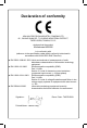
Declaration of conformity HON HAI PRECISION INDUSTRY COMPANY LTD 66 , CHUNG SHAN RD., TU-CHENG INDUSTRIAL DISTRICT, TAIPEI HSIEN, TAIWAN, R.O.C.
Declaration of conformity Trade Name: FOXCONN Model Name: Responsible Party: Address: Telephone: Facsimile: A85GM Equipment Classification: Type of Product: Manufacturer: Address: FCC Class B Subassembly Motherboard HON HAI PRECISION INDUSTRY COMPANY LTD 66 , CHUNG SHAN RD., TU-CHENG INDUSTRIAL DISTRICT, TAIPEI HSIEN, TAIWAN, R.O.C. PCE Industry Inc. 458 E. Lambert Rd.
Installation Precautions NING AR ! W ■ CA UT IO N ■ ! ■ ■ ■ ■ ■ ■ ■ ■ Electrostatic discharge (ESD) is the sudden and momentary electric current that flows between two objects at different electrical potentials. Normally it comes out as a spark which will quickly damage your electronic equipment. Please wear an electrostatic discharge (ESD) wrist strap when handling components such as a motherboard, CPU or memory.
Table of Contents Chapter 1 Product Introduction Product Specifications...............................................................................2 Layout.......................................................................................................4 Back Panel Connectors.............................................................................5 Chapter 2 Hardware Install Install the CPU and CPU Cooler...............................................................8 Install the Memory.........
About & Help.....................................................................................64 FOX LOGO..............................................................................................65 FOX DMI.................................................................................................66 Chapter 5 RAID Configuration RAID Configuration Introduction.............................................................69 Option ROM Utility..........................................................
Thank you for buying Foxconn A85GM Series motherboard. Foxconn products are engineered to maximize computing power, providing only what you need for break-through performance. With advanced overclocking capability and a range of connectivity features for today multi-media computing requirements, A85GM enables you to unleash more power from your computer.
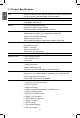
1 1-1 Product Specifications CPU Support the AMD PhenomII, Phenom, AMD Athlon II, Athlon, AMD Sempron processor families, AM2/AM2+/AM3 socket processors HyperTransport Up to 5200MT/s (HT3.
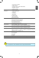
CA UT IO N Form Factor Micro ATX Form Factor, 9.6 inches x 9.6 inches (24.4cm x 24.4cm) ! The chipset driver of this motherboard does not support Windows® 2000. 1 1 x Front Audio connector 1 x IrDA connector 1 x Chassis intrusion alarm header (INTR) 1 x Speaker connector 1 x COM1 connector Back Panel 1 x PS/2 Mouse port Connectors 1 x PS/2 Keyboard port 1 x VGA port 1 x HDMI port 1 x DVI-D port 6 x USB 2.
1-2 Layout 1 4 3 2 1 5 6 25 7 8 24 9 23 10 22 11 21 12 13 14 15 16 17 18 1. 4-pin ATX 12V Power Connector 19 20 14. System Fan Header 15. COM1 Connector 16. ESATA Connector 17. IDE Connector 18. 24-pin ATX Power Connector 19. Floppy Connector 20. TPM Connector (Optional) 21. IrDA Connector 22. DDR2 DIMM Slots 23. North Bridge: AMD 785G 24. CPU Socket 25. CPU_FAN Header 2. PCI Express x1 Slot 3. PCI Express x16 Slot 4. PCI Slots 5. Front Audio Connector 6. CD_IN Connector 7.
1-3 Back Panel Connectors VGA Port 1 1 PS/2 Mouse Port LAN Port 7 3 Line Out Line In Rear Speaker Subwoofer Side Speaker Microphone 2 4 6 8 USB Ports Audio Ports 5 PS/2 Keyboard Port DVI-D Port HDMI Port 1. PS/2 Mouse Port Use the upper port (green) to connect a PS/2 mouse. 2. PS/2 Keyboard Port Use the lower port (purple) to connect a PS/2 keyboard. 3. VGA Port To connect with external display devices, such as monitor or LCD display. 4. DVI-D Port The DVI-D port supports DVI-D specification.
1 8. Audio Ports For the definition of each audio port, please refer to the table below : Port 2-channel 4-channel 5.1-channel 7.
This chapter introduces the hardware installation process, including the installation of the CPU, memory, power supply, slots, pin headers and the mounting of jumpers. Caution should be exercised during the installation of these modules. Please refer to the motherboard layout prior to any installation and read the contents in this chapter carefully.
CA UT IO N 2-1 Install the CPU and CPU Cooler ! 2 ■ ■ ■ ■ ■ ■ Read the following guidelines before you begin to install the CPU : Make sure that the motherboard supports the CPU. Always turn off the computer and unplug the power cord from the power supply before installing the CPU to prevent hardware damage. Locate the Pin-1 of the CPU. The CPU cannot be inserted if oriented incorrectly. Apply an even and thin layer of thermal grease on the surface of the CPU.
3. When CPU is properly seated, push the CPU socket lever back to its locked position. 2 Install the CPU Cooler Follow the steps below to correctly install the CPU cooler. (The following procedures use Foxconn cooler as the example.) CA UT IO N ! 1. Apply and spread an even thermal grease on the surface of CPU. 2. Buckle the heatsink firmly at one side of the stand. 3. Buckle the heatsink at another side, and press the fasten lever down to tightly seat the cooler. 4.
CA UT IO N 2-2 Install the Memory ! 2 ■ ■ ■ Read the following guidelines before you begin to install the memory : Make sure that the motherboard supports the memory. It is recommended that memory of the same capacity, brand, speed, and chips be used. Always turn off the computer and unplug the power cord from the power outlet before installing the memory to prevent hardware damage. Memory modules have a foolproof design. A memory module can be installed in only one direction.
CA UT IO N Installing a Memory ! Before installing a memory module, make sure to turn off the computer and unplug the power cord from the power outlet to prevent damage to the memory module. Be sure to install DDR2 DIMMs on this motherboard. 112-Pin 2 128-Pin Notch If you take a look at front side of memory module, it has asymmetric pin counts on both sides separated by a notch in the middle, so it can only fit in one direction.
CA UT IO N 2-3 Install an Expansion Card ! 2 ■ ■ Make sure the motherboard supports the expansion card. Carefully read the manual that came with your expansion card. Always turn off the computer and unplug the power cord from the power outlet before installing an expansion card to prevent hardware damage. PCI Express x1 PCI Express x16 PCI Follow the steps below to correctly install your expansion card in the expansion slot. 1. Locate an expansion slot that supports your card.
2-4 Install other Internal Connectors Power Connectors This motherboard uses an ATX power supply. In order not to damage any device, make sure all the devices have been installed properly before applying the power supply. 2 24-pin ATX power connector : PWR1 PWR1 is the ATX power supply connector. Make sure that the power supply cable and pins are properly aligned with the connector on the motherboard. Firmly plug the power supply cable into the connector and make sure it is secure.
Front Panel Connector : FP1 2 This motherboard includes one connector for connecting the front panel switch and LED Indicators. HDD-LED 1 + 2 - RESET-SW PWR-SW NC Hard Disk LED Connector (HDD-LED) Connect to the chassis front panel IDE indicator LED. It indicates the active status of the hard disks. This 2-pin connector is directional with +/- sign.
COM Connector : COM1 1 RLSD 2 SIN SOUT DTR GND DSR RTS CTS RI EMPTY 9 10 2 This motherboard supports one serial RS232 COM port for legacy compatibility. User must purchase another RS232 cable with a 9-pin D-sub connector at one end to connect with the external RS232 device and another end with 10pin female connector to connect with COM1 connector in the motherboard. COM1 IrDA Connector : IR This connector supports infrared wireless transmitting and receiving device.
Audio Connector : F_AUDIO The audio connector supports HD Audio standard. It provides the Front Audio output choice. PORT1_L PORT1_R PORT2_R SENSE_SEND PORT2_L 1 2 9 10 AUD_GND PRESENCE_J SENSE1_RETURN EMPTY SENSE2_RETURN 2 F_AUDIO CD_L GND CD_R Audio Connector : CD_IN CD_IN is a Sony standard audio connector, it can be connected to a CD/DVD-ROM drive through a CD/DVD audio cable. Fan Headers : CPU_FAN, SYS_FAN1, SYS_ FAN2 There are five main fan headers on this motherboard.
2-6 Jumpers For some features needed, users can change the jumper settings on this motherboard to modify them. This section explains how to use the various functions of this motherboard by changing the jumper settings. Users should read the following content carefully prior to modifying any jumper setting. 1. For any jumper on this motherboard, pin 1 can be identified by the bold silkscreen next to it. However, in this manual, pin 1 is simply labeled as “1”. 2.
This chapter tells how to change system settings through the BIOS Setup menus. Detailed descriptions of the BIOS parameters are also provided. You have to run the Setup Program when the following cases occur: 1. An error message appears on the screen during the system Power On Self Test (POST) process. 2. You want to change the default CMOS settings.
Enter BIOS Setup CA UT IO N The BIOS is the communication bridge between hardware and software, correctly setting up the BIOS parameters is critical to maintain optimal system performance. Power on the computer, when the message "Press to enter Setup, to boot menu". appears at the bottom of the screen, you can press key to enter SETUP. ! Main Menu The main menu allows you to select from a list of setup functions together with two exit choices.
3 ► Power Management Setup All the items related with Green function features can be set up through this menu. ► PC Health Status This setup enables you to read/change Fan speeds, and displays temperatures and voltages of your CPU/System. ► BIOS Security Features The Supervisor/User password can be set up through this menu to prevent unauthorized use of your computer. If you set a password, the system will ask you to key in correct password before boot or access to Setup.
System Information This sub-menu is used to set up the standard BIOS features, such as the date, time, floppy drive and so on. Use the arrow up/down keys to select an item, then use the <+> or <-> keys to change the setting. CMOS Setup Utility - Copyright (C) 1985-2006, American Megatrends, Inc. System Information 07 [Mon , 07/06/2009] Help Item [11 : 59 : 49] [Not Detected] Use [Enter], [TAB] or [SHIFT-TAB] to [Not Detected] select a field.
3 halt condition can be enabled/disabled in the next three settings. ► Keyboard The system boot will not stop for a keyboard error if you enabled this item. ► Mouse The system boot will not stop for a mouse error if you enabled this item. ► Floppy The system boot will not stop for a floppy error if you enabled this item. ► Model Name Model name of this product. ► BIOS ID It displays the current BIOS ID. User can check this information and discuss with the field service people if a BIOS upgrade is needed.
Advanced BIOS Features CMOS Setup Utility - Copyright (C) 1985-2006, American Megatrends, Inc. Advanced BIOS Features IDE Detect Time Out MPS Revision PCI Latency Timer Quiet Boot Quick Boot Bootup Num-Lock Floppy Drive Seek ► Boot Device Priority ► Removable Drives [5] [5] Help Item [1.1] [64] Select the time out [Enabled] value for detecting [Enabled] ATA/ATAPI device(s) [On] in second .
3 [Disabled] : Displays the normal POST messages. [Enabled] : Displays OEM customer logo instead of POST messages. ► Quick Boot While Enabled, this option allows BIOS to skip certain tests while booting, this will shorten the time needed to boot the system. ► Bootup Num-Lock This item defines if the keyboard Num Lock key is active when your system is started. The available settings are: On (default) and Off.
Fox Central Control Unit CMOS Setup Utility - Copyright (C) 1985-2006, American Megatrends, Inc.
► Smart Power LED Smart Power LED is a feature built on your motherboard to indicate different states during Power On System Test (POST). The LED is located at the front panel, and it displays POST state by different long-short blinking intervals. You can always leave this state enabled. 3 System Status Power LED Status Stop Blinking Condition Normal Always On Always On No Memory Continue blinking On (1sec.), Off (1sec.) Reboot & Memory OK No VGA Card detec Continue blinking On (2sec.
cache. The HyperTransport link width and frequency are initialized between the adjacent coherent and/or noncoherent HyperTransport technology devices during the reset sequence. It is highly recommended to set to [Auto] for overall performance. 27 3 contains important information about the module’s speed, size, addressing mode and various other parameters, so that the motherboard memory controller (chipset) can better access the memory device. Select [Auto] for SPD enable mode.
Voltage Options 3 CMOS Setup Utility - Copyright (C) 1985-2006, American Megatrends, Inc.
This menu shows most of the CPU specifications. ► Cool ’N’ Quiet This option helps lowering down the CPU frequency and voltage when system is idling. When the CPU speed is slowing down, the temperature will drop as well. ► C1E Support C1E represents Enhanced HALT State. It is a feature which CPU uses to reduce power consumption when in halt state. C1E drops the CPU’s multiplier and voltage to lower levels when a HLT (halt) command is issued. This item is used to enable/disable the C1E support.
Advanced Chipset Features CMOS Setup Utility - Copyright (C) 1985-2006, American Megatrends, Inc. Advanced Chipset Features Northbridge Chipset Configuration Help Item ► Memory Configuration [Press Enter] ► DRAM Timing Configuration [Press Enter] CAS Latency :5.
concept, wherein a static amount of page-locked graphics memory is allocated during driver initialization. This fixed amount of memory will provide the user with a guaranteed graphics memory at all times, and will no longer be available to the OS. ► Primary Video Controller This item is used to select which graphics controller is used as the primary boot device.
3 ■ DCT channels A and B can be ganged as a single logical 128-bit DIMM. ■ Offers highest DDR2 bandwidth. ■ Requires both DIMMs in a logical pair to have identical size and timing parameters, both DCTs programmed identically. Unganged channels ■ DCT channels A and B operate as two completely independent 64-bit channels (both channels operate at the same frequency). ■ Reduce DRAM page conflicts – more concurrent open dram pages . ■ Better bus efficiency.
Trfc0: auto-refresh row cycle time for logical DIMM 0 33 3 This item allows you to select the row precharge time (in clock cycles). ► tRTP (Internal Read to Precharge Command Delay) Internal READ Command to PRECHARGE Command delay. ► TRAS (Active-to-Precharge Delay) This item allows you to set the minimum RAS# active time (in clock cycles). ► TRC (Active-to-Active/Auto-Refresh Command Period) This item allows you to set the row cycle time (in clock cycles). tRC = tRAS + tRP.
Integrated Peripherals CMOS Setup Utility - Copyright (C) 1985-2006, American Megatrends, Inc. Integrated Peripherals Enter] Help Item [Press Enter] [Press Enter] [Press Enter] Configure the IDE [Press Enter] device(s).
USB Configuration CMOS Setup Utility - Copyright (C) 1985-2006, American Megatrends, Inc. USB Configuration USB Configuration Help Item Module Version - 2.24.3 -13.4 Enable support for legacy USB. Auto option disables legacy support if no USB devices are connected. USB Devices Enabled : None [Enabled] Legacy USB Support USB 2.
This item is used to set the transmission rate mode of USB 2.0. This function only works under DOS mode. The available settings are: [High Speed] in 480Mbps; [Full Speed] in 12Mbps. SuperIO Configuration CMOS Setup Utility - Copyright (C) 1985-2006, American Megatrends, Inc.
Trusted Computing CMOS Setup Utility - Copyright (C) 1985-2006, American Megatrends, Inc. Trusted Computing Trusted Computing Help Item [No] TCG/TPM SUPPORT [No] Enable/Disable TPM TCG (TPM 1.1/1.
Power Management Setup CMOS Setup Utility - Copyright (C) 1985-2006, American Megatrends, Inc. Power Management Setup [S3 (STR)] Help Item (STR)] [Power Off] [Enabled] Select the ACPI [Disabled] State used for [Disabled] System Suspend.
39 3 This item is used to set which state the PC will take with when it resumes after an AC power loss. ► HPET Support HPET stands for High Precision Even Timer. If you have the HPET disabled, then windows does not have access to it and therefore falls back to less accurate timing methods. This item is used to enable or disable the HPET Suppport. ► Resume by LAN This item is used to enable/disable the OnBoard LAN to generate a wake up.
PC Health Status 3 CMOS Setup Utility - Copyright (C) 1985-2006, American Megatrends, Inc. PC Health Status Warning Temperature Shut Down Temperature Case Open Warning CPU Temperature System Temperature CPU Fan Speed System Fan1 Speed System Fan2 Speed CPU Core DRAM Voltage +3.3V +12.0V +1.
BIOS Security Features CMOS Setup Utility - Copyright (C) 1985-2006, American Megatrends, Inc. BIOS Security Features Security Settings Supervisor Password : Not Installed User Password : Not Installed [Press Enter] Change Supervisor Password Help Item Install or change the password. 3 ↑↓←→:Move Enter:Select F1:General Help +/-/:Value F10:Save ESC:Exit F9:Optimized Defaults ► Change Supervisor Password This item is used to install or change supervisor password.
The utility CD that came with the motherboard contains useful software and several utility drivers that enhance the motherboard features. This chapter includes the following information: ■ Utility CD Introduction ■ Install driver and utility ■ FOX ONE ■ FOX LiveUpdate ■ FOX LOGO ■ FOX DMI Note : Because each module is independent, so the section number will be reorganized and unique to each module, please understand.
Utility CD Introduction This motherboard comes with one DVD. You can simply put it into your DVD-ROM drive, and the main menu will be displayed on your PC screen to guide you how to install. 1. Install Driver Use these options to install all the drivers for your system. You should install the drivers in order, and you need to restart your computer after all the drivers have been installed. A. AMD Chipset Driver B. Realtek HDA Audio Driver C. Realtek 811X LAN Driver D.
Install driver and utility 1. Install Driver You must click "AMD Chipset Driver" to install it first. After that, you can click ”One Click Setup” to install all the other drivers left, or you can click on each individual driver to install it manually. Manual Installation Step by Step 4 Automatic Installation by One Click. Exit the program Click to visit Foxconn's website Select to Install Utilities Select to In- Browse CD Drop to System Tray stall Drivers 2.
FOX ONE FOX ONE is a powerful utility for easily modifying system settings. It also allows users to monitor various temperature values, voltage values, frequencies and fan speeds at any time. CA UT IO N With FOX ONE, you can : ■ Modify system performance settings, such as the CPU and memory bus speeds, CPU voltages, fan speeds, and other system performance options. ■ Monitor hardware temperatures, voltages, frequencies and fan speeds.
1. Main Page Show CPU Information Toolbar Alert Lamp Switch Button Skin Button 4 Exit Minimum Configuration Homepage Monitor Frequency/Voltage/Fan speed/Temperature value Toolbar Use the toolbar to navigate to other pages. Alert Lamp When the system is in healthy state, the color of alert lamp is green. When the system is in abnormal state, the alert lamp color is red. Switch Button Click this button, it will simplify the whole FOX ONE control panel to a smaller information bar (i.e.
Skin Button There are more choices of FOX ONE screen panels. Click this button, you can select your favorite skin (FOX ONE Panel). Apply the changes Cancel the changes Exit Click this button to exit the program. Minimum Click this button to drop the FOX ONE to Windows system tray located at the lower right corner of your screen. Homepage Click this button to visit Foxconn motherboard website : http://www.foxconnchannel.
4 Configuration This menu allows you to configure : 1). Monitor interval (ms) : This is to define the interval of different messages of system settings which are to be displayed on Simple Mode screen. Minimum value is 1 second. 2). Simple Mode : To select which message of system settings are to be displayed in the Simple Mode. Messages such as CPU frequency, voltage...etc., they can be displayed one by one in Simple Mode. 3). F.I.S.
Step 1 : Click Calibration icon, a message pops out to ask for continue. Select Yes. 4 Step 2 : After data is collected, it will ask you to restart your computer now. Later on, when the FOX ONE program is activated, and F.I.S. feature (in CPU Page) is also enabled, FOX ONE will automatically adjust your CPU clock according to your system loadings. (Loadings are like Power Gaming, Data Mining...etc.
2. CPU Page - CPU Control 4 This page lets you select (or overclock) CPU clock to meet the current performance level of the system. The fastest and suitable CPU clock running for current system can be calculated by FOX ONE automatically or manually input by yourselves. Manual : You can press the up/down button to adjust your CPU clock. Auto : Click this button to let FOX ONE check the highest CPU clock you can use.
You can see the system is raising CPU clock until the system hangs. Push RESET button on the front panel of your system to restart the computer. 4 Run FOX ONE program again, it will inform you the previous test found that 255MHz is the recommended CPU clock for your system. Click Yes to apply it to your system. Now, your system is running at a CPU clock of 255MHz.
4 FOX Intelligent Stepping (F.I.S., Optional) Select FOX Intelligent Stepping will allow your system to automatically adjust your CPU clock rate based on different system loadings. For example, if you select Power Gaming, CPU clock will be driven to run at its maximum speed. While in Energy Saving, CPU will lower down its speed to a minimum.
4. Limit Setting 4.1 Limit Setting - CPU Temperature This page lets you to set CPU high limit temperature and enable the alert function. Go to Limit Setting page Show current CPU temperature value Enable alert function when the CPU temperature is higher than high limit value Set high limit by dragging the lever 4.2 Limit Setting - System Temperature This page lets you to set system high limit temperature and enable the alert function.
4.3 Limit Setting - CPU Fan This page lets you to set CPU fan low limit rpm and enable the alert function. Show current CPU fan rpm value 4 Enable alert function when the CPU fan runs slower than the low limit rpm value Show current low limit rpm value of CPU fan Set low limit rpm by dragging the lever 4.4 Limit Setting - System Fan This page lets you to set system fan low limit rpm and enable the alert function.
4.5 Limit Setting - FAN1 Fan This page lets you to set FAN1 fan low limit rpm and enable the alert function. Show current FAN1 fan rpm value Enable alert function when the FAN1 fan runs slower than low limit rpm value Set low limit rpm by dragging the lever 5. Voltage Page - Voltage Control (Optional) This page lets you set CPU voltage, memory voltage and North Bridge voltage manually. CPU voltage can be stepped up/down by a unit of 12.5mV, while memory is 0.05V/step, and North Bridge is 0.04V/step.
6. Fan Page - Fan Control This page lets you enable Smart Fan function or set the fan speed by manual. When Smart Fan is selected, you must use a 4-pin CPU cooler in your system.
FOX LiveUpdate FOX LiveUpdate is a useful utility to backup and update your system BIOS, drivers and utilities by local or online. Supporting Operating Systems : ■ Windows XP (32-bit and 64-bit) ■ Windows Vista (32-bit and 64-bit) 4 Using FOX LiveUpdate : 1. Local Update 1-1 Local Update - BIOS Information This page lets you know your system BIOS information. Minimum Link to website Exit Show current BIOS information Toolbar *** : please refer to the physical motherboard for detail.
1-2 Local Update - Backup This page can backup your system BIOS. You can click “Backup”, and key in a file name, then click “Save” to finish the backup operation. The extension of this backup file is ".BIN" for Award BIOS and ".ROM" for AMI BIOS. Default directory is "C:\Desktop\My Documents" in Windows XP and "Documents" in Vista. Make sure you can remember the file name together with the directory which it is stored, prevented that you may need them to recover your BIOS later.
2. Online Update 2-1 Online Update - Update BIOS This page lets you update your system BIOS from Internet. Click “start”, it will search the new BIOS from Internet. Then follow the wizard to finish the update operation. Click here Current information 4 Search new BIOS from Internet Select BIOS to update Browse detailed information Update BIOS Close the window 2-2 Online Update - Update Driver This page lets you update your system drivers from Internet.
Select the driver to update Browse detailed information Install the selected driver 4 Close the window 2-3 Online Update - Update Utility This page lets you update utilities from Internet. Click “start”, it will search the new utilities from Internet. Then follow the wizard to finish the update operation.
2-4 Online Update - Update All This page lets you update your system drivers from Internet. Click “start”, it will search all new BIOS/drivers/utilities from Internet. Then follow the wizard to finish the update operation.
3. Configure 3-1 Configure - option This page lets you set auto search options. After you enable the auto search function, FOX LiveUpdate will start its searching from Internet and if any qualified item found, it will pop out a message on the task bar to inform you to do the next step.
When you enable "Auto Search FOX LiveUpdate", if your FOX LiveUpdate version is older, it will auto search from internet and prompt you to install the new version. Prompt you to install the new FOX LiveUpdate 4 3-2 Configure - System This page lets you set the backup BIOS location and change different skin of the FOX LiveUpdate utility.
3-3 Configure - Advance This page lets you select to flash BIOS / Boot Block and clear CMOS. If you choose Flash Boot Block, it means BIOS is not protective, and you must make sure the flash process is continuous and without any interruption.
FOX LOGO FOX LOGO is a simple and useful utility to backup, change and delete the boot time Logo. The boot Logo is the image that appears on screen during POST (Power-On Self-Test). You can prepare a JPG image (1024x768) file, then use FOX LOGO to open it and change the boot time Logo. Boot time Logo will be displayed if you enable the BIOS "Quiet Boot" setting in "Advanced BIOS Features" menu.
FOX DMI FOX DMI is a full Desktop Management Interface viewer, and it provides three DMI data formats : Report, Data Fields and Memory Dump. With DMI information, system maker can easily analyze and troubleshoot your motherboard if there is any problem occurred. 4 Supporting Operating Systems : ■ Windows XP (32-bit and 64-bit) ■ Windows Vista (32-bit and 64-bit) Using FOX DMI: Please operate this utility as the comments shows. Click here to select the type you want to view.
This chapter will cover two topics : ■ ■ Creating a Bootable Array - Installing a new Windows XP (or Vista) in a brand new RAID system. Creating a Non-Bootable Array - Existing Windows XP (or Vista) system with new RAID built as data storage.
Creating a Bootable Array - Installing a new Windows XP (or Vista) in a brand new RAID system. 5 1. Follow 5-1 to create a RAID driver diskette. 2. Follow 5-2 to set RAID enabled in BIOS. 3. Follow 5-3 to select a RAID array for use. 4. Follow 5-4 to Install a new Windows Operating System. What kinds of hardware and software you need here : 1. A floppy drive. 2. A DVD-ROM drive. 3. Several SATA hard disks. 4. A RAID driver diskette. 5. A motherboard driver CD.
RAID Configuration Introduction RAID (Redundant Array of Independent Disks) is a method for computer data storage schemes that divide and/or replicate data among multiple hard drives. RAID can be designed to provide increased data reliability (fault tolerance) or increased I/O (input/ output) performance, or both. The following RAID configurations are provided for users. There are three major key concepts in RAID: 1. Mirroring : The copying of data to more than one disk; 2.
RAID 0 (Striped) RAID 0 reads and writes sectors of data interleaved among multiple drives. If any disk member fails, it affects the entire array. The disk array data capacity is equal to the number of drive members times the capacity of the smallest member. RAID 0 does not support fault tolerance. RAID 1 (Mirror) RAID 1 writes duplicate data onto a pair of drives and reads both sets of data in parallel.
Option ROM Utility The Option ROM Utility supports RAID 0, RAID 1 and RAID10 functions. It allows you to get high performance with fault tolerance, big capacity, or data safety provided by different RAID functions. Here, we will use four SATA hard disks as an example to guide you through how to configure your RAID system. Assume four hard disks are connected to the motherboard : SATA port 1 - HDS728090PLA380, 82.34GB SATA port 2 - WDC WD1200JD-98HBB0, 120.03GB SATA port 3- Hitachi HDT725025VLA3, 250.
Two topics will be covered in the following sections : 1). Creating a Bootable Array - Installing a new Windows XP in a brand new RAID system. 2). Creating a Non-Bootable Array - Existing Windows XP system with new RAID built as data storage. CA UT IO N Install SATA Hard Disks before we continue : ■ Shut down your computer. ■ Install SATA hard disks into the drive bays, connect all power and SATA cables.
5-1 Create a RAID Driver Diskette If you want to install a brand new Windows XP on a RAID system, you need to create a RAID driver floppy diskette which will be used during Windows XP installation later. 1. Find a PC, put a diskette into its floppy drive A:, this diskette will be formatted later. Put the driver CD into DVD-ROM drive. 3. Click "GO" to start. 4. Select the desired destination FDD drive. It can be the default drive A: or any USB FDD. Click "OK" to continue. 5.
6. You can input a volume label for this diskette, click on "Start" to format. 5 7. Click on "OK" to go through this warning message. 8. Format finished. Click "OK" to continue copying of RAID driver into this diskette. 9. Check if the diskette contains the driver files.
5-2 RAID Enable in BIOS 1. Enter the BIOS setup by pressing key when boot up. 2. Select the “Integrated Peripherals” from the “Main menu”, then select the “SATA Configuration” menu and press to go to the configuration items. 3. Enable RAID function and individual SATA port for hard drive or DVD connection. 4. Press to save the setting then PC will reboot itself. CMOS Setup Utility - Copyright (C) 1985-2006, American Megatrends, Inc.
Create RAID 0 (Striped) Here, we will show you how to create two RAID 0 Logical Drives (LD) by using two hard disks. 1. Select [2] from the main menu, "Define LD Menu" appears. Option ROM Utility (c) 2009 Advanced Micro Devices, Inc. [ Define LD Menu ] RAID Mode LD 1 LD 2 LD 3 LD 4 LD 5 LD 6 LD 7 LD 8 LD 9 LD10 RAID −−−− 0 −−−− −−−− −−−− −−−− −−−− −−−− −−−− −−−− −−−− Total Drv Capacity(GB) 2 −−−− −−−− −−−− −−−− −−−− −−−− −−−− −−−− −−−− −−−− 163.
5. A message prompts. Press [Ctrl-Y] to erase the RAID array. Fast Initialization Option has been selected It will erase the MBR data of the disks, 6. Another screen prompts. Press [Ctrl-Y]. Input 80GB to select the first logical drive (LD1) and press [Enter]. Press Ctrl-Y to Modify Array Capacity or press any other key to use maximum capacity... Option ROM Utility (c) 2009 Advanced Micro Devices, Inc.
8. When LD2 is selected, press [Enter] to continue. Option ROM Utility (c) 2009 Advanced Micro Devices, Inc. [ Define LD Menu ] RAID Mode LD 1 LD 2 LD 3 LD 4 LD 5 LD 6 LD 7 LD 8 LD 9 LD10 RAID 0 −−−− −−−− −−−− −−−− −−−− −−−− −−−− −−−− −−−− Total Drv Capacity(GB) 2 −−−− −−−− −−−− −−−− −−−− −−−− −−−− −−−− −−−− 79.
10. A message prompts. Press [Ctrl-Y] to erase the RAID array. Option ROM Utility (c) 2009 Advanced Micro Devices, Inc. [ Define LD Menu ] LD No RAID Mode LD 2 RAID 0 Total Drv 2 Stripe Block: 64 KB Gigabyte Boundary: ON Fast Init: Cache Mode: ON WriteThru Fast Initialization Option has been selected Channel :ID Drive Model Compatibilities Capacity(GB) Assignment It will erase the MBR data of the3G disks, 1 :Mas HDS728090PLA380 SATA 42.
Create RAID 1 (Mirror) Here, we will show you how to create one Mirrored Logical Drives (LD) by using two hard disks. 1. Select [2] from the main menu, "Define LD Menu" appears. Option ROM Utility (c) 2009 Advanced Micro Devices, Inc. [ Define LD Menu ] RAID Mode LD 1 LD 2 LD 3 LD 4 LD 5 LD 6 LD 7 LD 8 LD 9 LD10 RAID −−−− 0 −−−− −−−− −−−− −−−− −−−− −−−− −−−− −−−− −−−− Total Drv 2 −−−− −−−− −−−− −−−− −−−− −−−− −−−− −−−− −−−− −−−− Capacity(GB) 163.
5. A message prompts. Press [Ctrl-Y] to erase the RAID array. Fast Initialization Option has been selected It will erase the MBR data of the disks, 6. Another screen prompts. Press any key to use the maximum capacity. Option ROM Utility (c) 2009 Advanced Micro Devices, Inc.
Create RAID 10 (Striped Mirror) Here, we will show you how to create one Striped Mirror Logical Drives (LD) by using four hard disks. 1. Select [2] from the main menu, "Define LD Menu" appears. Option ROM Utility (c) 2009 Advanced Micro Devices, Inc. [ Define LD Menu ] RAID Mode LD 1 LD 2 LD 3 LD 4 LD 5 LD 6 LD 7 LD 8 LD 9 LD10 RAID −−−− 0 −−−− −−−− −−−− −−−− −−−− −−−− −−−− −−−− −−−− Total Drv 2 −−−− −−−− −−−− −−−− −−−− −−−− −−−− −−−− −−−− −−−− Capacity(GB) 163.
5. A message prompts. Press [Ctrl-Y] to erase the RAID array. Fast Initialization Option has been selected It will erase the MBR data of the disks, 6. Another screen prompts. Press any key to use the maximum capacity. Option ROM Utility (c) 2009 Advanced Micro Devices, Inc.
Create RAID Ready A "RAID Ready" system is a specific system configuration that, with the addition of a second Serial ATA hard drive, can be seamlessly migrated to a configuration that provides either improved storage performance or data protection from a single hard drive failure. 1. Select [2] from the main menu, "Define LD Menu" appears. Option ROM Utility (c) 2009 Advanced Micro Devices, Inc.
5. A message prompts. Press [Ctrl-Y] to erase the RAID array. Option ROM Utility (c) 2009 Advanced Micro Devices, Inc. [ Define LD Menu ] LD No RAID Mode LD 1 RAID READY Total Drv 1 Stripe Block: NA Gigabyte Boundary: NA Fast Init: Cache Mode: ON WriteThru Fast Initialization Option has been selected Channel :ID Drive Model Compatibilities Capacity(GB) Assignment It will erase the MBR data of the3G disks, 1 :Mas HDS728090PLA380 SATA 42.
Create JBOD Here, we will show you how to create a JBOD Logical Drives (LD) by using four hard disks. 1. Select [2] from the main menu, "Define LD Menu" appears. Option ROM Utility (c) 2009 Advanced Micro Devices, Inc. [ Define LD Menu ] RAID Mode LD 1 LD 2 LD 3 LD 4 LD 5 LD 6 LD 7 LD 8 LD 9 LD10 RAID −−−− 0 −−−− −−−− −−−− −−−− −−−− −−−− −−−− −−−− −−−− Total Drv Capacity(GB) 2 −−−− −−−− −−−− −−−− −−−− −−−− −−−− −−−− −−−− −−−− 163.
5. A message prompts. Press [Ctrl-Y] to erase the RAID array. Option ROM Utility (c) 2009 Advanced Micro Devices, Inc. [ Define LD Menu ] LD No LD 1 RAID Mode Total Drv JBOD 4 Stripe Block: 64 KB Gigabyte Boundary: ON Fast Init: Cache Mode: ON WriteThru Fast Initialization Option has been selected Channel :ID Drive Model Compatibilities Capacity(GB) Assignment It will erase the MBR data of the3G disks, 1 :Mas HDS728090PLA380 SATA 42.
5-4 Install a New Windows XP Assume a Mirrored array (249.99GB) was created as introduced in section 5-3, after the system restarts : 1. Press to enter BIOS Setup during POST. 2. Insert the Windows installation CD into the optical drive. 3. Set the “1st Boot Device” to “CD/DVD-ROM”, save changes and exit BIOS. CMOS Setup Utility - Copyright (C) 1985-2006, American Megatrends, Inc.
5. After some files are copied to your system, the following picture appears, press to continue the specific driver installation. Windows Setup Setup could not determine the type of one or more mass storage devices installed in your system, or you have chosen to manually specify an adapter.
7. There are two drivers, for your 32-bit XP system, press [Enter] to select the first driver - "AMD AHCI Compatible RAID Controller-x86 platform". Windows Setup You have chosen to configure a SCSI Adapter for use with Windows, using a device support disk provided by an adapter manufacturer. Select the SCSI Adapter you want from the following list, or press ESC to return to the previous screen.
9. Windows will display the partition of your system. As we are using a Mirrored RAID array as an example, its size 232.88GB is now displayed as 238410MB. You can press [C] to create partitions as many as you wish, assign them C:, D: or E: logical drive names. (Note : 238410MB/1024 = 232.82GB) Windows XP Professional Setup The following list shows the existing partitions and unpartitioned space on this computer. Use the UP ad DOWN ARROW keys to select an item in the list.
5-5 Setting Up a Non-Bootable RAID Array This section assumes the following setup : ■ Boot Disk with Windows XP installed : One hard disk HDS728090PLAT20 (80GB) is connected to the IDE channel, and set to Master. ■ A Mirrored RAID Array Disk : Two SATA hard disks are configured as a mirrored RAID1 array, they are : Hitachi HDT725025VLA3, (250.05GB) connected to SATA port2 of the motherboard. Seagate ST3320620AS, (320.07GB) connected to SATA port3. ■ A SATA DVD Drive : A DVD drive connected to SATA port1.
2. Select a RAID array for use (also can refer to section 5-3) After rebooting your computer, you will see the RAID software prompting you to press [Ctrl-F]. Press [Ctrl-F] to enter the Option ROM Utility and configure the mirrored RAID array as described in the 5-3 section. Finally, you can reach this step as depicted. Option ROM Utility (c) 2008 Advanced Micro Devices, Inc.
5 5. After the AMD RAID driver is installed, it will ask you to click "Finish" to restart your computer. 6. When Windows starts, a message is prompting you to reboot again. Click "Yes" to restart your computer.
7. After PC starts, the RAID array is now ready to be initialized under Windows. Launch Computer Management by clicking Start -> (Settings ->) Control Panel then open the Administrative Tools folder and double click on Computer Management. Click Disk Management (under the Storage section). The Initialize and Convert Disk Wizard appears. Click "Next" to continue. The RAID array is named as Disk1 and its status is unknown and not initialized. 5 8. A "Select Disks to Initialize" window will appear.
5 11. The Computer Management window appears. The actual disks listed will depend on your system. In below figure, you can see there is a 232.82 GB unallocated partition. You must format the unallocated disk space before using it. Right click "Unallocated space", select "New Partition…" and follow the Wizard instructions. 12. When "New Partition Wizard" appears, click "Next" to continue. 13. When "Primary partition" screen appears, click "Next" to continue. 14.
17. The format of disk array (Disk1) is in processing. 5 18. Format completed, now you can start using your RAID array.