7870 Interfacility Link Installation and User’s Guide © Copyright 2008
This manual contains propriety and confidential information of Foxcom Reproduction, release to any third party, or any other unauthorized use, of any information contained herein is expressly forbidden. The information contained in this document is believed to be accurate as of the time of going to press. Specifications are subject to change without notice. Corporate Office Israel US Office South Africa Office Beck Science Center 8 Hartom Street, Har Hotzvim P.O.
Table of Contents Important Information . . . . . . . . . . . . . . . . . . . . . . . . . . . . . . . . . . . . . iii Chapter 1 Introduction to the 7870 Interfacility Link ..................................... 1 1.1 1.2 1.3 1.4 Options . . . . . . . . . . . . . . . . . . . . . . . . . . . . . . . . . . . . . . . . . . . . . . . . . . .2 Product Drawings . . . . . . . . . . . . . . . . . . . . . . . . . . . . . . . . . . . . . . . . . .3 Panel Descriptions. . . . . . . . . . . . . . . . . . . . . . . . . .
Figures Figure 1 Figure 2 Figure 3 Figure 4 Figure 5 Figure 6 Figure 7 Figure 8 Figure 9 Figure 10 Figure 11 Figure 12 Figure 13 Figure 14 Figure 15 Figure 16 Figure 17 Figure 18 Figure 19 Figure 20 Figure 21 Figure 22 Figure 23 Figure 24 Figure 25 Figure 26 Figure 27 Figure 28 Figure 29 Figure 30 Figure 31 Figure 32 Figure 33 Figure 34 Figure 35 Figure 36 Option Label. . . . . . . . . . . . . . . . . . . . . . . . . . . . . . . . . . . . . . . . . . . . . . . . . . . . . . . . . . .
Important Information Important Information Warranty and Repair Policy . . . . . . . . . . . . . . . . . . . . . . . . . . . . . . . . . . . . . . . iii General Warranty . . . . . . . . . . . . . . . . . . . . . . . . . . . . . . . . . . . . . . . . . . . . . . iii Specific Product Warranty Instructions . . . . . . . . . . . . . . . . . . . . . . . . . . . . . . iii Returns . . . . . . . . . . . . . . . . . . . . . . . . . . . . . . . . . . . . . . . . . . . . . . . . . . . . . .
Important Information Returns In the event that it is necessary to return any product against above warranty, the following procedure shall be followed: 1. Return authorization is to be received from Foxcom prior to returning any unit. Advise Foxcom of the model, serial number, and discrepancy. The unit may then be forwarded to Foxcom, transportation prepaid. Devices returned collect or without authorization may not be accepted. 2.
Important Information Reporting Defects The units were inspected before shipment and found to be free of mechanical and electrical defects. Examine the units for any damage which may have been caused in transit. If damage is discovered, file a claim with the freight carrier immediately. Notify Foxcom as soon as possible. Note Keep all packing material until you have completed the inspection.
Important Information page vi Document no.
1 Introduction to the 7870 Interfacility Link 1.1 1.2 1.3 1.4 Options . . . . . . . . . . . . . . . . . . . . . . . . . . . . . . . . . . . . . . . . . . . . . . . . 2 Product Drawings. . . . . . . . . . . . . . . . . . . . . . . . . . . . . . . . . . . . . . . . 3 Panel Descriptions . . . . . . . . . . . . . . . . . . . . . . . . . . . . . . . . . . . . . . . 4 Block Diagrams . . . . . . . . . . . . . . . . . . . . . . . . . . . . . . . . . . . . . . . . .
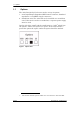
1.1 Options 1.1 Options The 7870 Interfacility Link comes with a variety of options: 1. 50 Ω Input/Output Impedance/BNC female connector; Standard impedance is 75 Ω/BNC, female connectors. 2. Standalone unit; The 7870 IFL can be installed as a standalone unit. If the 7870 is used as a standalone, a separate power supply must be used. On the side of the 7870T and the 7870R units is a label1 which lists the options. Under each option is a square.
1.2 Product Drawings 1.
1.3 Panel Descriptions 1.3 Panel Descriptions On the Front Panel of the 7870 IFL units are two LEDs. Both LEDs should be on when the unit is in use.
1.4 Block Diagrams 1.
1.4 Block Diagrams page 6 Document no.
2 Installation Chapter 2 describes how to install the 7870 Interfacility Link units. Setting up the 7870E Transmitter/Receiver consists of: 2.1 2.2 2.3 2.4 2.4.1 2.5 2.6 Setting up the Transmitter. . . . . . . . . . . . . . . . . . . . . . . . . . . . . . . . . 8 Connecting the Fiber Optic Cable. . . . . . . . . . . . . . . . . . . . . . . . . . . 9 Setting Up the Receiver . . . . . . . . . . . . . . . . . . . . . . . . . . . . . . . . . . 10 Powering the IFL. . . . . . . . . . . . . . . . . . . . . . .
2.1 Setting up the Transmitter 2.1 Setting up the Transmitter 1. Place the 7870T in the 7180M Chassis. 2. Apply AC power to the chassis. The Power Supply and Laser LEDs should be lit. 3. Using an optical power meter, measure the optical power. Insert the meter’s cable into the Transmitter’s optical connector. Power levels should be 0.5 mW minimum (-3 dBm).
2.2 Connecting the Fiber Optic Cable 2.2 Connecting the Fiber Optic Cable Before connecting the cable: 1. The fiber optic cable must be either fusion spliced or connected via FC/APC connectors. 2. Wipe the connector with a lint-free cotton cloth. 3. Note the polarity key of the optical connector before inserting. To connect the cable: 1. Line Up the Polarity Key. 2. Insert the connector 3.
2.3 Setting Up the Receiver 2.3 Setting Up the Receiver 1. Place the 7870R Receiver in any of the 7180M Chassis, unless a 2040 RF Switch is installed. (See Figure 7 7180M Chassis Rear View on page 12.) Note If a 2040 RF Switch(es) is being installed, then slots 2 and/or 5 of the 7180M are reserved for the switch(es). 2. Apply AC power to the chassis. The Power Supply’s LED should be lit. 3. Using an optical power meter, measure the optical power coming to the Receiver from the fiber optic cable.
2.4 Powering the IFL 2.4 Powering the IFL • • • • Transmitter power requirement: +14 VDC @ 200 mA Receiver power requirement: +14 VDC @ 250 mA. The Standalone Transmitter/Receiver is powered by a Foxcom supplied external DC power supply. The Rackmount Transmitters/Receivers are plugged into the rackmount chassis. The chassis can accept and power up to eight units. Note At temperatures below10°C, the Transmitter’s internal heater will require an additional 100 mA.
2.4 Powering the IFL 2.4.1 7180M Chassis The 7180M Chassis provides power to the plug in units. The power supply is a switching type. Each plug-in regulates its own voltage.
2.5 Connecting the Back Panel Jumpers 2.5 Connecting the Back Panel Jumpers On the rear panel of the 7180M Back Panel are product selectors (JP1 to JP4). The 3 pin selectors (male) are the connecting point between the slots and the back panel. One pin is for the transmitter/receiver (Tx/Rx), one is for the optional 2040 1:1 Redundant Switch, and one is for the 7180M. A 2 pin jumper (female) is placed on the relevant pins to complete the connection between the 7180M and the units.
2.5 Connecting the Back Panel Jumpers 4. If the 2040 Switch is installed in Slot 5, place the JP1 and JP2 jumpers on the lower two pins and the JP3 and JP4 jumpers on the higher two pins. Figure 10 Jumper Installation: 2040 Switch in slot 5 5. If the 2040 Switch is installed in Slots 2 and 5, place the JP1, JP2, JP3, and JP4 jumpers on the higher two pins.
2.6 Aligning the Fiber Optic Link 2.6 Aligning the Fiber Optic Link The final step in installing the 7870 Interfacility Link is re-adjusting the Receiver Gain Control for unity gain. To set the unity gain (standard version) 1. Set the Signal Generator to -15 dBm. Alternatively measure the operational input level. 2. Set up the system as shown in Figure 12 Fiber Optic Alignment Setup 3. Adjust the Receiver Gain Control for -15 dBm reading on the power meter.
2.6 Aligning the Fiber Optic Link page 16 Document no.
3.1 7870 Interfacility Link Specifications 3 Product Specifications 3.1 3.2 3.3 7870 Interfacility Link Specifications . . . . . . . . . . . . . . . . . . . . . . . 17 Model Dimensions . . . . . . . . . . . . . . . . . . . . . . . . . . . . . . . . . . . . . . 19 7870 Interfacility Link Pinouts. . . . . . . . . . . . . . . . . . . . . . . . . . . . . 20 3.3.1 3.3.2 3.4 Transmitter Pinout. . . . . . . . . . . . . . . . . . . . . . . . . . . . . . . . . . . . . . . . . . . . 20 Receiver Pinouts . . . .
3.1 7870 Interfacility Link Specifications Optical Specifications Optical Wavelength 1310 ± 10 nm Optical power output 0.5 mW/-2 dBm [minimum] Optical connector FC/APC Optical budget / distance 16 dB / 40 Km Optical return loss -60 dB Optical connector loss 0.5 dB/mated pair Physical Specifications Chassis capacity 8 plug-ins, and 2 power supplies Chassis size 19” × 3U × 7” Power for rackmount [max.] 100 to 240 VAC 50/60Hz 90 Watts Standalone size 5” × 4.8” × 1.
3.2 Model Dimensions 3.
3.3 7870 Interfacility Link Pinouts 3.3 7870 Interfacility Link Pinouts 3.3.
3.3 7870 Interfacility Link Pinouts 3.3.
3.4 7180M Chassis Pinouts 3.4 7180M Chassis Pinouts The unit’s pins are found at the backplane of the 7180M chassis. The 7180M chassis backplane incorporates eight slots. Pinouts from the 9-pin connector at each slot are sent through the backplane assembly to the two 25-pin D-connectors, J12 and J13, and one 9-pin connector, J113. Any monitor voltages to be measured may be done between the chassis ground and the required pin.
3.4 7180M Chassis Pinouts 3.4.1 7180M Alarm Connector Pinouts [J12] Pin No. Function Name Slot No.
3.4 7180M Chassis Pinouts 3.4.
4 Troubleshooting The 7870D Interfacility Link unit was tested before it left the factory. However if you are experiencing difficulties see the list below for possible solutions. if you are still experiencing problems, attempt to isolate and identify the malfunctioning unit before consulting Foxcom’s technical support. Table 8 Troubleshooting the Transmitter Problem Possible Cause 1. Laser LED not on a. No DC power to the unit. Possible power supply problem or AC power input problem.
Table 9 Troubleshooting the Receiver Problem Possible Cause 1. Lack of RF signal present at Receiver, yet optical power is functioning. If a spectrum analyzer or power meter is not available then use a DVM and adjust the gain control for RF signal strength (RSSI) so that the reading is > 0.2VDC. (See Table 5 7870R Receiver Pinout on page 21). Conclusion: If signal still not present then transmitter input stage amplifier or receiver amplifier is defective. Contact factory. 2. No optical power, a.
Appendix 1 Cleaning Fiber Optic Connections Appendix 1.1 Cleaning Procedures for FC/APC Connectors ....................... 28 Appendix 1.2 Cleaning Procedure for FC/APC Bulkhead Ports................... 29 Appendix 1.2.1 Swab Method ........................................................................................... 29 Appendix 1.2.2 Compressed Air Method .........................................................................
Appendix 1.1 Cleaning Procedures for FC/APC Connectors Appendix 1.1 Cleaning Procedures for FC/APC Connectors Use a Kim Wipe to gently wipe the end face surface of the connector. Alternatively a Cletop automatic connector cleaner can be used. Figure 19 Wiping the connector with a Kim wiper Figure 20 Wiping the connector with a Kim wiper [2] page 28 Document no.
Appendix 1.2 Cleaning Procedure for FC/APC Bulkhead Ports Appendix 1.2 Caution Cleaning Procedure for FC/APC Bulkhead Ports Clean the transmitter and receiver optical ports only when there is evidence of contamination or reduced performance. Appendix 1.2.1 Swab Method Using a clean fiber optic cleaning swab, gently wipe out the optical port. Discard the swab after use. Figure 21 Cleaning the Optical Port Figure 22 Cleaning the Optical Port [2] Appendix 1.2.
Appendix 1.2 Cleaning Procedure for FC/APC Bulkhead Ports page 30 Document no.
Appendix 2 Installing a Standalone Unit To install the 7870T-STD or 7870R--STD Standalone: 1. 2. 3. 4. Place the 7870 unit on the standalone flange, matching the holes. Using four screws (#4 or #6) secure the unit and the flange to the wall. Apply AC power to the standalone power supply unit. Connect the 7870 unit to the power supply. The Laser LED should be lit. All remaining steps are the same as in the product manual. See sections 2.1 Setting up the Transmitter on page8 and 2.
page 32 Document no.
Appendix 3 The 2380 Relay Adapter Appendix 3.1 Installing the 2380 Relay Adapter .................................... 34 Appendix 3.1.1 Parts Required for Installing the 2380 .............................................. 34 Appendix 3.1.2 Mounting the the 2380 Relay Adapter .............................................. 34 Appendix 3.2 2380 Dimensions and Front Panel Label......................... 36 Appendix 3.3 2380 Adapter Pinouts ........................................................
Appendix 3.1 Installing the 2380 Relay Adapter Appendix 3.1 Installing the 2380 Relay Adapter Appendix 3.1.1 Parts Required for Installing the 2380 •2380 Relay Adapter •Two pin guides •Four one-inch screws •Screw driver Appendix 3.1.2 Mounting the the 2380 Relay Adapter 1. Very Important: Disconnect the electricity before performing this procedure. 2. Make sure that you have all the needed equipment. 3. Install the pin guides. Figure 23 Installing the guide pins 4.
Appendix 3.1 Installing the 2380 Relay Adapter 5. Mount the four screws. The screws must be installed in the order shown in Figures 25 and 26. Figure 25 Mounting the Screws [1] Figure 26 Mounting the screws [2] Figure 27 Mounted 2380 Adapter Caution Use only the mounting screws provided by Foxcom.
Appendix 3.2 2380 Dimensions and Front Panel Label Appendix 3.2 page 36 2380 Dimensions and Front Panel Label Figure 28 2380 Dimensions Figure 29 2380 Front Label Document no.
Appendix 3.3 2380 Adapter Pinouts Appendix 3.3 2380 Adapter Pinouts Table 11 2380 Alarms Pinouts [J2] Pin Number Function Name Slot Number 1 2 3 4 5 6 7 8 9 10 11 12 13 14 15 16 17 18 19 20 21 22 23 24 25 Alarm Alarm Alarm Alarm Alarm Alarm Alarm Alarm Alarm Alarm Alarm Alarm Alarm Alarm Alarm Alarm NOP1 COM1 NOP2 COM2 NOP3 COM3 NOP4 COM4 NOP5 COM5 NOP6 COM6 NOP7 COM7 NOP8 COM8 1 1 2 2 3 3 4 4 5 5 6 6 7 7 8 8 Main PS Alarm Standby PS Alarm Power Supply Comm.
Appendix 3.3 2380 Adapter Pinouts Table 12 Pin # Function Name Slot No.
Appendix 4 Pinout Charts and Diagrams Figures 31 through 36 give detailed pinout information for the 7180M chassis, the 2380 Relay Adaptor and the 2040 RF Switch. Figure 31 Figure 32 Figure 33 Figure 34 Figure 35 Figure 36 Standard 7180M and 7180M with 2380 Relay Adapter Pinout . . . . . . . . . . . . . . . . . . . 7180M and 2040 RF Switch Pinout . . . . . . . . . . . . . . . . . . . . . . . . . . . . . . . . . . . . . . . . Pinout of 7180M Jumper with 2040 RF Switch in slots 2 and 5 . . . . . . . . . .
7180M Monitor Connector Pinouts (J13) P1 15VDC P2 Spare P3 GND P4 RSSI1 P5 PDI1 P6 LSRI1/Spare* P7 RFAlm1 P8 OptAlm1 Tx/Rx A3/J1 J13P1 J13P9 J13P17 J12P1 J12P9 P9 LNB1** Tx/Rx A2/J1 P1 RSSI1 A1J1P7 P1 RFAlm1 A2J1P4 P2 RSSI2 P2 RSSI2 A2J1P7 P2 RFAlm2 P1 RF-OptAlm1 P2 RF-OptAlm1 A3J1P4 P3 RSSI3 P3 RSSI3 A3J1P7 P3 RFAlm3 P3 RF-OptAlm2 A4J1P4 P4 RSSI4 P4 RSSI4 A4J1P7 P4 RFAlm4 P4 RF-OptAlm2 A5J1P4 P5 RSSI5 P5 RSSI5 A5J1P7 P5 RFAlm5 P5 RF-OptAlm3 A6J1P4 P6 RSSI6 P6 RSSI6 A6J1P7
7180M Alarm Connector Pinouts (J12) 7180M Monitor Connector Pinouts (J13) 7180M LNB Powering Connector Pinouts (J11) A1J1P4 P1 RSSI1 Not functional in this setup A1J1P7 P1 RFAlm1 Not functional in this setup Not functional in this setup A3J1P4 P3 RSSI3 A3J1P7 P3 RFAlm3 Not functional in this setup A4J1P4 P4 RSSI4 Not functional in this setup A4J1P7 P4 RFAlm4 Not functional in this setup Not functional in this setup A6J1P4 P6 RSSI6 A6J1P7 P6 RFAlm6 A7J1P4 P7 RSSI7 A7J1P7 P7 RFAlm7 A
Figure 33 Pinout of 7180M Jumper with 2040 RF Switch in slots 2 and 5 page 42 Document no.
Figure 34 Pinout of 7180M jumper with 2040 RF switch in slot 5 7870 Interfacility Link Installation and User’s Guide Foxcom proprietary information page 43
Figure 35 Pinout of 7180M jumper with 2040 RF switch in slot 5 page 44 Document no.
Figure 36 Pinout of 7180 jumper with transmitter and receiver units only 7870 Interfacility Link Installation and User’s Guide Foxcom proprietary information page 45
page 46 Document no.