NETBOX User’s Manual
Trademark: All trademarks are the property of their respective owners. Version: User’s Manual V1.0 for NETBOX. P/N: 3A222V700-000-G ! ARNING Caution : refers to important information that can help you to use NETBOX better, and tells you how to avoid problems. ! W CA UT IO N Symbol description: Warning: indicating a potential risk of hardware damage or physical injury may exist. WEEE: The use of this symbol indicates that this product may not be treated as household waste.
CA UT IO N Safety Notice : ! Before using this product, please read the below safety notice carefully, this will help to extend the product’s lifecycle, and work normally. ■ When NETBOX is working, please make sure its ventilation system is working. ■ The power adapter is dissipating heat during normal use, please be sure not to cover it and keep it away from your body to prevent discomfort or injury by heat exposure.
Table of Contents Chapter 1 Introduction of NETBOX Product Overview......................................................................................2 LED Indicator Introduction.........................................................................4 Chapter 2 Placement and connection of NETBOX Placement of NETBOX On the Desk..........................................................................................6 On the Display Back..........................................
The NETBOX is a compact and easy to use desktop. It features all the desktop capabilities but with a slim body design which enables your to browse the internet in a relaxable and comfortable way.
1 NETBOX features all the desktop capabilities but with a slim body design which enables you to browse the internet in a relaxable and comfortable way. 1-1 Product Overview 1. Top View (190mm) 7.5in 5.3in (135mm) 2. Front Side View 0.95in (24mm) LLS_LED1 1 2 3 4 5 LLS_LED5 6 7 8 9 No. Name Description 1 Headphone Port Connects to a headphone 2 Microphone In and S/PDIF In Port Connects to a microphone or playback devices with optical connectors(3.
3. Back Side View 1 1 2 4 3 5 6 7 No. Name Description 1 RF(Radio Frequency) Port Connects to antenna 2 USB Ports Connect to USB devices 3 Display Output Port(VGA) Connects to display device 4 HDMI Port Connects to HDMI audio and video 5 Network Port Standard RJ-45 network port 6 Line Out and S/PDIF Out Port Connects to powered analog speakers or recording devices with optical connectors(3.5mm jack) 7 Power Input Port Connects to the power adapter 4. Bottom View 1 No.
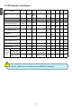
1 1-2 LED Indicator Introduction Indication Suspend_ Power_ HDD_ WLAN_ LLS_ LLS_ LED LED LED LED Boot - Green Red Blink - - - S0(Working Mode) - Green - - Off Off S1(Power-Saving Mode) - Green Off - Off Off Red Blink - Off - Off Off - Off Off - Off CPU Initialization Error - - - - DRAM Error - - - - S3(Standby Mode) [Press Suspend Button] S4(Hibernation Mode)& S5(System Power Off Mode) LLS_ LLS_ LLS_ LED1 LED2 LED3 LED4 LED5 - - - Off Off Off Off
In this chapter, the placement and the connection of some necessary peripherals will be introduced.
2-1 Placement of NETBOX 1. On the Desk You can install your NETBOX in the mount directly. 2 If there is enough space on your desk, you can simply put your NETBOX with Magnet-Metal- Feet on the tabletop. 2. On the Display Back CA UT IO N This is the best space-saving way. 2.1. Use four screws(M4X10mm) to fasten the bracket onto the display back. ! To install this bracket, your display must follow VESA75/VESA100 standard.
2.2. Fit the NETBOX into the bracket with power button locating at the top for easy touch. 2 2 1 CA UT IO N 2.3. After that, you can connect the antenna to your NETBOX. ! Remove the antenna before lifting up the NETBOX straight to take it out.
2-2 Connection of NETBOX 1. Connect the Antenna Connect the antenna to the RF port of the NETBOX. You can fold the antenna and rotate it in different angle as you want. 2 1 2 2. Connect the Monitor Connect a monitor to the NETBOX through VGA connector or HDMI connector. 3. Connect the USB Devices Connect USB devices to the USB ports of the NETBOX, for example, mouse and keyboard.
4. Connect the Network Cable Connect LAN cable to the RJ-45 port, with the other end connected to a hub or switch. 2 Hub or Switch 5. Connect the Power Cord Connect the power adapter to the power input port of the NETBOX, and push the power button to start it. 2 Outlet 3 CA UT IO N 1 ! The power adapter is dissipating heat during normal use, please make sure not to cover it and keep it away from your body to prevent discomfort or injury from heat exposure.
This chapter introduces the following information: ■ Install Windows XP ■ Install Windows 7 ■ Appendix - Display Features Notice
CA UT IO N Make sure you have these ready : 1. NETDVD. (It is an optional accessory. If there is no NETDVD in this package, you need other purchase an external USB DVD-ROM drive.) 2. NETBOX driver CD. (In this package) 3. Windows XP Install CD/Windows 7 Install CD. (Other purchase) ! Before we continue : ■ Your NETBOX power is off. ■ Connect the NETDVD or USB DVD-ROM drive. 3-1 Install Windows XP 1. Install Windows XP 1.1.
1.4. The computer will reboot, and it will start installing Windows XP Operating System. Windows XP Professional Setup Welcome to Setup. This portion of the Setup program prepares Microsoft(R) Windows(R) XP to run on your computer. ● To set up Windows XP now, press ENTER. 3 ● To repair a Windows XP installation using Recovery Console, press R. ● To quit Setup without installing Windows XP, press F3. ENTER=Continue R=Repair F3=Quit 1.5.
1.8. In this biggest hard disk size screen, you can press [C] to create partitions as you wish, assign them C:, D: or E: logical drive names. Windows XP Professional Setup The following list shows the existing partitions and unpartitioned space on this computer. Use the UP ad DOWN ARROW keys to select an item in the list. ● To set up Windows XP on the selected item, press ENTER. ● To create a partition in the unpartitioned space, press C. ● To delete the selected partitions, press D.
2. Install Drivers in Windows XP 3 2.1. When the Windows XP is completely installed, you have to install the necessary drivers before using the NETBOX. Take out the Windows XP Install CD from the DVD-ROM drive, and put the NETBOX driver CD inside. 2.2. Waiting for a few seconds, the main menu will be displayed, click “Driver” to enter the Driver menu shown as below: 2.3. Use these options to install all the drivers for your system. You must click "Intel Chipset Driver" to install it first.
3-2 Install Windows 7 1. Install Windows 7 1.1. Push power button to turn on your computer, then press key to enter BIOS Setup. 1.2. Put the Windows 7 Install CD into the NETDVD or USB DVD-ROM drive. 1.3. Select and go to the “Boot” menu, enter “Boot Device Priority”, set the “1st Boot Device” to “USB: Optical DVD RW”, press key to save change and exit BIOS.
3 1.8. Later the setup will display the hard disk partitions of your system. If there were other systems (such as Linux) installed previously, you need select them and click “Drive options (advanced)” to delete them. When all partitions are clean, setup will display the biggest size of your hard drive. 1.9. In this biggest hard disk size screen, you can click “New” button to create partitions as you need.
To ensure that all Windows features work correctly, Windows might create an additional partitions for system files, so you will see a system reserved partition. Select the 70GB partition and click “Next” to continue. 3 1.10. From this step we start to install windows 7 into your hard disk, including copying Windows files, expanding Windows files...etc. During the installation, your computer will restart several times.
3 1.11. When the installation is completed, setup will prepare your compute for the first use. Then you can follow steps to select system settings, create an account, set a password...etc, until the whole process is completed and enter Windows 7 operating system. 2. Install Drivers in Windows 7 2.1. When the Windows 7 is completely installed, you have to install the necessary drivers before using the NETBOX.
Appendix - Display Features Notice 1. Chrontel HDMI Display Settings and Scaling Some HDMI TV will display overscan mode as below, you can adjust it by using the Chrontel HDMI Tool which appears after installing “Chrontel Control Driver”, otherwise, it can also be used for the display resolution settings. CA UT IO N 3 ! HDMI port support hotplug detecting, and the resolution support is base on the reading EDID information! 1.1. The resolution can be chosen from the drop-down list. 1.2.
3 Note: Click the “HDMI On” button in the left can close the HDMI output, you can reopen it by re-plugging the HDMI cable. 2. Display Instruction in OS(Windows XP/Vista/7) 2.1. In the Intel® Graphics Media Accelerator Driver, the VGA(D-sub) port is defined as “Monitor”, and the HDMI port is defined as “Notebook”. 2.2.
2.3. For the VGA user, after installing VGA Driver, and rebooting into system, the VGA default Operating Mode is "Intel(R) Dual Display Clone", and the "Screen resolution" is held to “1280 x 720”. If you want to adjust the screen resolution, please follow the steps below to select the “Single Display” in "Operating Mode”. Step 1. Double click the Intel® Graphics Media Accelerator Driver icon in the system tray. 3. HD Video Play Notice If you want to play HD videos, the .WMV, .MOV and .
Statement: This device complies with part 15 of the FCC Rules. Operation is subject to the following two conditions: (1) This device may not cause harmful interference, and (2) this device must accept any interference received, including interference that may cause undesired operation. Warning: FEDERAL COMMUNICATIONS COMMISSION INTERFERENCE STATEMENT This equipment has been tested and found to comply with the limits for a Class B digital device, pursuant to part 15 of the FCC Rules.