nT-i2000 series NanoPC User’s Manual
Trademark: All trademarks are the property of their respective owners. Version: User’s Manual V1.1 for nT-i2000 series NanoPC. ! ARNING ! W CA UT IO N Symbol description: Caution : refers to important information that can help you to use NanoPC better, and tells you how to avoid problems. Warning: indicating a potential risk of hardware damage or physical injury may exist. WEEE: The use of this symbol indicates that this product may not be treated as household waste.
CA UT IO N Safety Notice : ! Before using this product, please read the below safety notice carefully, this will help to extend the product’s lifecycle, and work normally. ■ When NanoPC is working, please make sure its ventilation system is working. ■ The power adapter is dissipating heat during normal use, please be sure not to cover it and keep it away from your body to prevent discomfort or injury by heat exposure.
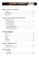
Table of Contents Chapter 1 Introduction of NanoPC Top View....................................................................................................2 Front Side View.........................................................................................2 Back Side View.........................................................................................3 Bottom View..............................................................................................
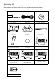
Accessory List Thanks for choosing our products. Please check the accessories listed below. If there is anything broken or lost, please contact with your distributors as soon as possible. Power Adapter Power Cord Magnet Rubber Foot Vesa Mount Seatbase Opening Tool 3.90mm 8.00mm 9.70mm Mini PCIe Half Card Support Screw for Half MiniPCI Card (M:4.4X2.85mm)(1X) 2.43mm 2.85mm 4.40mm USB Flash Disk 2.42mm Screw for HDD Support Bracket (M:4.7X2.85mm)(4X) 4.40mm 2.92mm 4.70mm 2.
This chapter introduces NanoPC’s outlook : ■ Top View ■ Front Side View ■ Back Side View ■ Bottom View
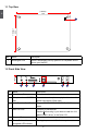
1-1 Top View 1 (190mm) 7.5in 1 5.3in (135mm) No. 1 Name Description Kensington Lock Attach a Kensington security system or a compatible lock to secure your NanoPC 1-2 Front Side View 24mm 1 No. Name 2 3 4 5 6 Description 1 Headphone Port Connects to a headphone 2 Microphone In and S/PDIF In Port Connects to a microphone or playback devices with optical connectors(3.5mm jack) 3 Multi-Function Card Reader Support SD/SDHC/SDXC/MS/MS Pro/MMC memory cards 4 USB 3.
1-3 Back Side View 1 1 2 3 4 5 6 No. Name Description 1 USB 2.0 Ports Connects to USB devices 2 Display Output Port (VGA) Connects to display device 3 HDMI Port Connects to HDMI audio and video 4 Network Port Standard RJ-45 network port 5 Line Out and S/PDIF Out Port Connects to powered analog speakers or recording devices with optical connectors(3.5mm jack) 6 Power Input Port Connects to the power adapter 1-4 Bottom View 1 No.
In this chapter, the placement and the connection of some necessary peripherals will be introduced.
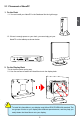
2-1 Placement of NanoPC 1. On the Desk 1.1. You can install your NanoPC in the Seatbase like the right image. 2 1.2. If there is enough space on your desk, you can simply put your NanoPC on the tabletop as shown below. 2. On the Display Back CA UT IO N This is the best space-saving way. 2.1. Use four screws to fasten the Vesa Mount onto the display back. ! To install this Vesa Mount, your display must follow VESA75/VESA100 standard.
2 2.2. Fit the NanoPC into the Vesa Mount with power button locating at the top for easy touch. 2 CA UT IO N 1 ! Lift up the NanoPC straightly to take it out.
2-2 Connection of NanoPC 1. Connect the Monitor Connect a monitor to the NanoPC through VGA connector. 2 2. Connect the USB Devices Connect USB devices to the USB ports of the NanoPC, for example, mouse and keyboard. 3. Connect the Network Cable Connect LAN cable to the RJ-45 port, with the other end connected to a hub or switch.
4. Connect the Power Cord Connect the power adapter to the power input port of the NanoPC, and push the power button to start it. 2 1 Outlet 3 CA UT IO N 2 ! The power adapter is dissipating heat during normal use, please make sure not to cover it and keep it away from your body to prevent discomfort or injury from heat exposure.
This chapter tells how to change system settings through the BIOS Setup menus. Detailed descriptions of the BIOS parameters are also provided. You have to run the Setup Program when the following cases occur : 1. An error message appears on the screen during the system Power On Self Test (POST) process. 2. You want to change the default Item settings.
Enter BIOS Setup ! We do not suggest that you change the default values in the BIOS Setup, and we shall not be responsible for any damage which resulted from the change you made. 3 CA UT IO N The BIOS is the communication bridge between hardware and software, correctly setting up the BIOS parameters is critical to maintain optimal system performance.
Main Menu The BIOS Setup is accessed by pressing the button after the Power-On Self-Test (POST) memory test begins and before the operating system boot begins. Once you enter the BIOS Setup Utility, the Main Menu will appear on the screen. The Main Menu provides System Overview information and allows you to set the System Time and Date. Use the “←” and “→” cursor keys to navigate between menu screens. Aptio Setup Utility - Copyright (C) 2012 American Megatrends, Inc.
Advanced Aptio Setup Utility - Copyright (C) 2012 American Megatrends, Inc. Main Advanced Power Security BootOptions Save & Exit ▶ Miscellaneous ▶ Integrated Periperals ▶ SATA Configuration 3 Miscellaneous ↑ ↓→ ←: Move Enter: Select +/-: Change Opt ESC: Exit F1: General Help F2: Previous Values F3: Optimized Defaults F4: Save & Exit Setup F7: Load User-defined Defaulta F8: Save as User-defined Version 2.15.1231. Copyright (C) 2012 American Megatrends, Inc.
Integrated Peripherals Aptio Setup Utility - Copyright (C) 2012 American Megatrends, Inc. Main Advanced Power Security BootOptions Save & Exit USB Configuration Onboard USB3.0 Controller [Enabled] PCH Azalia Configuration Azalia [Enabled] Enable/Disable Onboard USB3.0 Controller. 3 ↑ ↓→ ←: Move Enter: Select +/-: Change Opt ESC: Exit F1: General Help F2: Previous Values F3: Optimized Defaults F4: Save & Exit Setup F7: Load User-defined Defaulta F8: Save as User-defined Version 2.15.1231.
SATA configuration Aptio Setup Utility - Copyright (C) 2012 American Megatrends, Inc. Main Advanced Power Security BootOptions Save & Exit [Enabled] [AHCI] Enable/Disable SATA Device. 3 SATA Controller(s) SATA Mode Selection ↑ ↓→ ←: Move Enter: Select +/-: Change Opt ESC: Exit F1: General Help F2: Previous Values F3: Optimized Defaults F4: Save & Exit Setup F7: Load User-defined Defaulta F8: Save as User-defined Version 2.15.1231. Copyright (C) 2012 American Megatrends, Inc.
Power Aptio Setup Utility - Copyright (C) 2012 American Megatrends, Inc. Main Advanced Power Power Security BootOptions Save & Exit Restore On AC Power Loss Deep Sleep Support [Last state] [Enabled] Set the restore on AC power loss function Version 2.15.1231. Copyright (C) 2012 American Megatrends, Inc. ► Restore on AC Power Loss This item is used to set which state the PC will take with when it resumes after an AC power loss.
Power Aptio Setup Utility - Copyright (C) 2012 American Megatrends, Inc. Main Advanced Power Power Security BootOptions Save & Exit [Last state] [Disabled] [Disabled] Select ACPI sleep state the system will enter when the SUSPEND button is pressed.
Security Aptio Setup Utility - Copyright (C) 2012 American Megatrends, Inc. Main Advanced Power Security Security BootOptions Save & Exit Administrator Password Status User Password Status Not Installed Not Installed Change Supervisor Password ME Flash Write Protect [Enabled] Valid Keys: (1)a-z (A-Z) (2)0~9 (3)11 special keys:-=[];,.
BootOptions 3 Aptio Setup Utility - Copyright (C) 2012 American Megatrends, Inc. Main Advanced Power Security BootOptions Save & Exit ▶ ▶ ▶ ▶ Launch CSM Launch PXE OpROM policy [Enabled] [Do not launch] FIXED BOOT ORDER Priorities 1st Boot Device 2nd Boot Device 3rd Boot Device 4th Boot Device [Hard Disk] [CD&DVD] [USB 2.
Save & Exit Aptio Setup Utility - Copyright (C) 2012 American Megatrends, Inc. Main Advanced Power Security BootOptions Save Save & & Exit Exit Save Changes and Exit Discard Changes and Exit Save Changes Discard Changes Load Default Values Save as User Default Values Load User Default Values Exit system setup after saving the changes. Version 2.15.1231. Copyright (C) 2012 American Megatrends, Inc.
3 ► Load User Default Values If you select this option and press , a message will be displayed in the screen. Select [Yes] to restore/load the user defaults to all the setup options, select [No] or to return to the menu.
This chapter introduces the following information: ■ Install Windows 7/8 ■ Install Drivers in Windows 7/8
Make sure you have these ready : 1. NETDVD. (It is an optional accessory. If there is no NETDVD in this package, you need other purchase an external USB DVD-ROM drive.) 2. NanoPC driver. (USB Flash Disk is in this package) 3. Windows 7/8 Install CD. (Other purchase) 4 CA UT IO N Before we continue : ■ Your NanoPC power is off. ■ Connect the NETDVD or USB DVD-ROM drive. ! ■ WiFi card with this product doesn't support Vista operating system.
5. After that, it will start Windows and come out a “Install Windows” dialog box to set the “Language to install”, “Time and current format” and “ Keyboard or input method”. Click “Next” to continue and click “Install now” button to start the setup. 6. When the license terms appear, select to accept and click “Next” to continue. 7. It then asks you to select the installation type. Click “Custom (advanced)” to install a new copy of Windows. 4 8.
4 9. In this biggest hard disk size screen, you can click “New” button to create partitions as you need. In this example, we will create a 70GB partition to install Windows, and click “Apply”. To ensure that all Windows features work correctly, Windows might create an additional partitions for system files, so you will see a system reserved partition. Select the 70GB partition and click “Next” to continue.
10. From this step we start to install Windows 7/8 into your hard disk, including copying Win dows files, expanding Windows files...etc. During the installation, your computer will restart several times. 4 11. When the installation is completed, setup will prepare your compute for the first use. Then you can follow steps to select system settings, create an account, set a password...etc, until the whole process is completed and enter Windows 7/8 Operating System.
Install Drivers in Windows 7/8 4 1. When the Windows 7/8 is completely installed, you have to install the necessary drivers before using the NanoPC. Connet the USB Flash Disk.(USB Flash Disk is in this package) 2. Waiting for a few seconds, the main menu will be displayed, click “Driver” to enter the Driver menu shown as below: 3. Use these options to install all the drivers for your system. You must click "Intel Chipset Driver" to install it first.
This chapter introduces the following information: ■ FOX WinFlash
FOX WinFlash FOX WinFlash is a useful utility to backup and update your system BIOS. Supporting Operating Systems : ■ ■ ■ Windows XP (32-bit/64-bit) Windows 7 (32-bit/64-bit) Windows 8 (32-bit/64-bit) Using FOX WinFlash: 5 1. Local Update 1-1 Local Update - BIOS Information This page lets you know your system BIOS information.
1-2 Local Update - Backup This page can back up your system BIOS. You can click “Backup BIOS”, and key in a file name, then click “Save” to finish the backup operation. The extension of this backup file is “.ROM” for AMI BIOS. Make sure you can remember the file name together with the directory which it is stored, prevented that you may need them to recover your BIOS later. Key in a BIOS name Click here 5 1-3 Local Update - Update This page helps you to update your BIOS from a local file.
2. About & Help This page shows some information about FOX WinFlash.
Statement: This device complies with part 15 of the FCC Rules. Operation is subject to the following two conditions: (1) This device may not cause harmful interference, and (2) this device must accept any interference received, including interference that may cause undesired operation. Warning: FEDERAL COMMUNICATIONS COMMISSION INTERFERENCE STATEMENT This equipment has been tested and found to comply with the limits for a Class B digital device, pursuant to part 15 of the FCC Rules.