Trademarks FOXWELL is trademark of Shenzhen Foxwell Technology Co., Ltd. All other marks are trademarks or registered trademarks of their respective holders. Copyright Information ©2019 Shenzhen Foxwell Technology Co., Ltd. All rights reserved. Disclaimer The information, specifications and illustrations in this manual are based on the latest information available at the time of printing. Foxwell reserves the right to make changes at any time without notice. Visit our website at: www.foxwelltech.
One-Year Limited Warranty Subject to the conditions of this limited warranty, Shenzhen Foxwell Technology Co., Ltd (“FOXWELL”) warrants its customer that this product is free of defects in material and workmanship at the time of its original purchase for a subsequent period of one (1) year.
TO LOSS OF ANTICIPATED BENEFITS OR PROFITS, LOSS OF SAVINGS OR REVENUE, LOSS OF DATA, PUNITIVE DAMAGES, LOSS OF USE OF THE PRODUCT OR ANY ASSOCIATED EQUIPMENT, COST OF CAPITAL, COST OF ANY SUBSTITUTE EQUIPMENT OR FACILITIES, DOWNTIME, THE CLAIMS OF ANY THIRD PARTIES, INCLUDING CUSTOMERS, AND INJURY TO PROPERTY, RESULTING FROM THE PURC HASE OR USE OF THE PRODUCT OR ARISING FROM BREACH OF THE WARRANTY, BREACH OF CONTRACT, NEGLIGENCE, STRICT TORT, OR ANY OTHER LEGAL OR EQUITABLE THEORY, EVEN IF FOXWELL KNEW OF
Safety Information For your own safety and the safety of others, and to prevent damage to the equipment and vehicles, read this manual thoroughly before operating your code reader. The safety messages presented below and throughout this user’s manual are reminders to the operator to exercise extreme care when using this device. Always refer to and follow safety messages and test procedures provided by vehicle manufacturer. Read, understand and follow all safety messages and instructions in this manual.
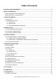
Table of Contents ONE-YEAR LIMITED WARRANTY.................................................................................................................... 2 SAFETY INFORMATION......................................................................................................................................4 SAFETY MESSAGE CONVENTIONS USED...............................................................................................................4 IMPORTANT SAFETY INSTRUCTIONS.......................
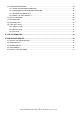
7.2 CONFIGURE MONITORS......................................................................................................................... 34 7.2.1 SPARK IGN REQUIRED MONITORS......................................................................................................... 35 7.2.2 COMPRESSION IGN REQUIRED MONITORS........................................................................................ 36 7.2.3 ALLOWED INC MONITORS..................................................................
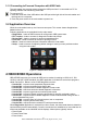
1 Using This Manual We provide tool usage instructions in this manual. Below are the conventions we used in the manual. 1.1 Bold Text Bold text is used to highlight selectable items such as buttons and menu options. Example: Press the ENTER button to select. 1.2 Symbols and Icons 1.2.1 Solid Spot Operation tips and lists that apply to specific tool are introduced by a solid spot●. Example: When System Setup is selected, a menu that lists all available options displays.
2 Introduction NT301 is developed by the most distinguished mind of the industry. It is specially designed to support all 10 OBDII service modes, including live data, O2 sensor test and more, on OBDII/EOBD compliant cars, SUVs, light-duty truck and mini-vans sold worldwide since 1996. 2.1 Code Reader Descriptions This section illustrates external features, ports and connectors of the code reader. Figure 2-1 Front View A. OBD II Cable - provides communication for vehicle DLC. B.
K. BACK Key - cancels an action and returns to previous screen or level. L. ENTER Key - confirms an action or movement and moves to next level. M. Power Switch - reboot the code reader N. HELP Key - accesses to the Help function and it is also used to update the code reader when long pressed. O. USB Port – provides a USB connection between the code reader and PC or laptop. 2.2 Accessory Descriptions This section lists the accessories that go with the code reader.
3.1.2 Connecting to Personal Computer with USB Cable The code reader also receives power through the USB port when it is connected to a PC for updating software and transferring saved files. To connect to PC: 1. Insert the small end of the USB cable to the USB port at the right side of the code reader and the large end to a computer. 2. Press the power switch of the code reader to power it on. 3.2 Application Overview When the code reader boots up, the Home screen opens.
● ● ● ● ● ● ● ● Live Data I/M Readiness O2 Sensor Test On-board Monitor Test Component Test Vehicle Information Modules Present Unit of measure NOTE Not all function options listed above are applicable to all vehicles. Available options may vary by the year, model, and make of the test vehicle. A “The selected mode is not supported!” message displays if the option is not applicable to the vehicle under test.
Read Codes menu lets you read stored codes, pending codes and permanent does found in the control unit. Typical menu options include: ● Stored Codes ● Pending Codes ● Permanent Codes Diagnostic trouble codes stored in a control module are used to help identify the cause of a trouble or troubles with a vehicle. These codes have occurred a specific number of times and indicate a problem that requires repair. Pending codes are referred to as maturing codes that indicate intermittent faults.
Figure 4-5 Sample DTC Description Screen NOTE If no DTCs are present, the message “No (Pending) Codes Found!” is displayed. If any manufacturer specific or enhanced codes detected, NT301 reads the correct DTC information automatically according to the VIN. 4.2 Erase Codes Erase Codes menu lets you to clear all current and stored DTCs from the control module. Also it erases all temporary ECU information, including freeze frame.
Figure 4-7 Sample Erase Codes Screen 3. Check the codes again. If any codes remain, repeat the Erase Codes steps. 4.3 Live Data Live Data menu lets you view, record and playback real time PID data from the electronic control module. Menu options typically include: ● View Data ● Record Data ● Playback Data 4.3.1 View Data The View Data function allows real time viewing of the vehicle’s electronic control unit’s PID data, including sensor data, operation of switches, solenoids and relays.
Figure 4-9 Sample Live Data Menu Screen 3. Select Complete Data Set from the menu and press the ENTER key to display the datastream screen. Figure 4-10 Sample View Data Menu Screen 4. Scroll with the up and down arrow keys to scroll through data to select lines, and left and right arrow keys to scroll back and forth through different screens of data. Figure 4-11 Sample Complete List Screen 5. Press the ENTER key to view PID graph if the PID gives a numeric reading.
Figure 4-12 Sample PID Graph Screen 6. Use the BACK key to return to diagnostic menu. 4.3.1.2 Custom Data List Custom Data List menu lets you to minimize the number of PIDs on the data list and focus on any suspicious or symptom-specific data parameters. To create a custom data list: 1. Select Custom List from the menu and press the ENTER key. Figure 4-13 Sample Live Data Menu Screen 2. The custom datastream selection screen displays. Figure 4-14 Sample Custom Datastream Selection Screen 3.
Figure 4-15 Sample Custom Datastream Screen 4. When finished selection, press the ENTER key to display selected items. Figure 4-16 Sample Datastream Screen 4.3.2 Record Data The Record Data function is used to record PIDs to help diagnose intermittent drivability problems that can’t be determined by any other method. Menu options typically include: ● Complete Data ● Custom Data ● Unit of measure (Please refer to Chapter 7 Set Up) NOTE There are two types of trigger methods used.
Figure 4-17 Sample Live Data Menu Screen 2. Refer to View Data to set up Complete Data Set or Customer Data Set to record. Figure 4-18 Sample Record Data Menu Screen 3. Scroll with the up and down arrow keys to pick a trigger mode and press the ENTER key to confirm. Figure 4-19 Sample Pick Trigger Mode Screen 4. Use the UP/DOWN key to select a memory location and press ENTER to confirm. 18 NT301 OBDII/EOBD Code Reader User’s Guide_English Version_V1.
Figure 4-20 Sample Select Memory Screen NOTE The asterisk (*) on the screen indicates that a recording currently exists in this memory location. If an area with an asterisk (*) was picked, a message prompting to erase data displays. Figure 4-21 Sample Erase Recording Screen 5. If the recording is to be overwrited, selected Yes; if data is not to be overwrited, pick No to return to Select Memory screen and choose another one. 6.
Figure 4-23 Sample DTC Trigger Recording Screen 8. Press the ENTER key to start recording or wait codes to trigger. Figure 4-24 Sample Recording Screen NOTE Different vehicles communicate at different speeds and support a different number of PIDs. Therefore, the maximum number of frames that can be recorded varies. The code reader keeps recording data until ● the memory is full. ● the operator presses the BACK key. 9. After recording, the code reader displays a prompt to Playback.
To playback data: 1. Scroll with the up and down arrow key to select Playback Data from the Menu. Figure 4-26 Sample Record Data Screen 2. Use the UP/DOWN key to select a memory area that is marked with an asterisk (*) and press the ENTER to confirm. Figure 4-27 Sample Record Data Screen 3. Press the UP/DOWN key to view recorded PIDs of each frame. Press the BACK key to exit. Figure 4-27 Sample Record Data Screen 4.
Figure 4-28 Sample Diagnostic Menu Screen 2. Use the up and down arrow keys to scroll through data to select lines, and left and right arrow keys to scroll back and forth through different screens of data. If no freeze frame detected, the message “No freeze frame data stored!” is displayed. Figure 4-29 Sample Freeze Data Screen 3. Use the BACK key to return to Diagnostic Menu。 4.
4 5 6 7 8 9 10 Catalyst Mon Htd Catalyst Evap System Mon Sec Air System A/C Refrig Mon Oxygen Sens Mon Oxygen Sens Htr 11 EGR System Mon Catalyst Monitor Heated Catalyst Monitor Evaporative System Monitor Secondary Air System Monitor Air Conditioning Refrigerant Monitor Oxygen Sensor Monitor Oxygen Sensor Heater Monitor Exhaust Gas Recirculation System Monitor There are two ways to retrieve I/M Readiness Status data: ● One-click I/M readiness key ● Typical way: select I/M Readiness from Diagnostic Menu
● Red - four short beeps. NOTE The built-in beeper which makes different tones corresponding to different LED indicators is invaluable when the test is performed while driving or in bright areas where LED illumination may not be visible. To retrieve I/M Readiness Status data by typical way: 1.Scroll with UP/DOWN key to highlight I/M Readiness from Diagnostic Menu and press the ENTER key. If vehicle supports both types of monitors, a screen for monitor type selection displays.
Figure 4-32 Sample IM Readiness Screen 1 Or Figure 4-33 Sample IM Readiness Screen 2 4.6 O2 Monitor Test OBD II regulations require certain vehicles monitor and test oxygen (O2) sensors to isolate fuel and emissions related faults. The O2 Monitor Test function is used to retrieve completed O2 sensors monitor test results. The O2 Monitor Test is not an on-demand test. O2 sensors are not tested when selected via the menu but tested when engine operating conditions are within specified limits.
Figure 4-35 Sample O2 Monitor Test screen 3. Use the up and down arrow keys to scroll through data to select lines, and left and right arrow keys to scroll back and forth through different screens of data. Figure 4-36 Sample O2 Bank1 Sensor 1 Screen 4. Press ENTER key to view data of selection. Figure 4-37 Sample data of $81 screen 5. Press the BACK key to exit and return. 4.7 On-Board Monitor Test The On-Board Monitor Test function is useful after servicing or after clearing a vehicle ECU’s memory.
Test results do not necessarily indicate a faulty component or system. To request on-board monitor test results: 1. Use the UP/DOWN key to highlight On-Board Monitor Test from Diagnostic Menu and press the ENTER key. Figure 4-38 Sample Diagnostic Menu Screen 2. Depending on the protocol the vehicle used, one of these 2 screens shows. Or Figure 4-39 Sample Non-CAN Vehicle Test Screen Figure 4-40 Sample CAN vehicle test screen 3.
Figure 4-41 Sample Non-CAN vehicle test screen For CAN vehicles, test screen is illustrated as below: Figure 4-42 Sample Can vehicle test screen 4. Press the BACK key to exit and return. 28 NT301 OBDII/EOBD Code Reader User’s Guide_English Version_V1.
4.8 Component Test Component Test allows the code reader to control operation of vehicle components, tests or systems. NOTE ● Some manufacturers do not allow tools to control vehicle systems. ● The manufacturer sets the criteria to automatically stop test. Refer to appropriate vehicle service manual before using this function. To perform a component test: 1.Use the UP/DOWN key to highlight Component Test from Diagnostic Menu and press the ENTER key. A screen with a list of available tests displays.
Available options will vary depending on the vehicle under test. To request vehicle information: 1.Use the UP/DOWN key to highlight Vehicle Info. from Diagnostic Menu and press the ENTER key. Figure 4-45 Sample Diagnostic Menu Screen 2.Follow on-screen instruction and send the command to read vehicle information. A screen with a list of available options displays. Figure 4-46 Sample Vehicle Info Screen 3.Use the UP/DOWN key to highlight an available option and press the ENTER key.
The code reader identifies module IDs and communication protocols for OBD2 modules in the vehicle. To view module IDs and communication types: 1.Use the UP/DOWN key to highlight Modules Present from Diagnostic Menu and press the ENTER key. Figure 4-48 Sample Diagnostic Menu Screen 2.A screen with the module IDs and protocols displays. Figure 4-49 Sample Module Present Screen 3.Press the BACK key to exit and return. 5.
Figure 5-1 Sample Home Screen 2. Use the LEFT/RIGHT key to select the desired character, then press the UP/DOWN key to change the digit you want to enter a valid code number. Press the ENTER key to confirm. Figure 5-2 Sample DTC Lookup Screen 3. A screen with code number and its definition displays.
To review recorded data: 1. Use the LEFT/RIGHT key to highlight Review Data from home screen and press the ENTER key. Figure 6-1 Sample Home Screen 2. A screen with a list of test records displays. If no data is recorded, the message “No Data available!” is displayed. Figure 6-2 Sample Playback Screen 3. Use the UP/DOWN key to highlight an optional record and press the ENTER key. Details of the test record displays. View and analysis the recorded information, then press BACK to exit.
Figure 7-1 Sample Home Screen 2.A screen of a list of menu options displays. Figure 7-2 Sample Setup Screen 3.Press the UP/DOWN key select a language and press the ENTER key to confirm. Press the BACK key to exit and return. Figure 7-2 Sample Language Selection Screen 7.2 Configure Monitors This menu allows the users to configure the monitors required to test spark ignition and compression ignition, the number of monitors to pass diagnosis, and restore the default settings.
● Reset Factory Default There are two different types of monitors: continuous and non-continuous. Continuous monitors are different in design from the non-continuous monitors. Continuous monitors are being constantly tested and evaluated by the car’s computer while the car is running. Conversely, the non-continuous monitors require certain conditions to be met before a test or series of tests can be completed.
Figure 7-4 Sample Configure Monitors Display 7.2.1 Spark IGN Required Monitors In this menu, the operators can configure monitors for spark ignition cars (gasoline engines). To configure spark IGN required monitors: 1. Use the UP/DOWN key to highlight Spark IGN Required Monitors from menu and press the ENTER key to confirm. 2. The custom monitors selection screen displays. Figure 7-5 Sample Custom Monitors Selection Screen 3.
7.2.2 Compression IGN Required Monitors In this menu, the operators can configure monitors for compression ignition cars (diesel engines). To configure spark compression required monitors: 1. Use the UP/DOWN key to highlight Compression IGN Required Monitors from the menu and press the ENTER key to confirm. Figure 7-7 Sample Configure Monitors Display 2. The custom monitors selection screen displays and Use the RIGHT key to select or deselect a monitor or press the LEFT key to deselect all the monitors.
Figure7-8 Sample Configure Monitors Selection Screen 2. The custom INC monitors selection screen displays and scroll with the up and down arrow keys to select. Press the ENTER key to confirm and BACK key to cancel. Figure 7-9 Sample Allowed INC Monitors Selection Screen 7.2.4 Reset Factory Default This menu will allow the users to restore the default configuration settings in the Configure Monitors menu, and delete any customized settings.
2. A message prompting to reset factory default displays. Answer Yes to confirm the request or answer No to abort and return. Figure7-11 Sample Reset Factory Default Screen 7.3 Unit of measure Unit of measure opens a dialog box that allows you to choose between US customary or metric units of measure. To change the unit setup: 1. Scroll the UP/DOWN keys to highlight Unit of Measure from Setup menu and press the ENTER key. Figure 7-12 Sample Setup Screen 2.
Key beep set opens a dialog box that allows you to turn on/off the built-in speaker for key pressing. To set the key beep: 1. Use the UP/DOWN key to highlight Key beep set from Setup menu and press the ENTER key. Figure 7-14 Sample Setup Screen 2. Press the UP/DOWN arrow key select an item and press the ENTER key to save and return. Figure 7-15 Sample Beep Set Selection Screen 7.
Figure 7-17 Sample Diag Beep Selection Screen 7.6 Tool Self-test Key beep set opens a dialog box that allows you to check if the LCD display and the operation of keypad and LED are working correctly. Typical menu includes: ● Display Test ● Keypad Test ● LED Test 7.6.1 Display Test Selecting Display Test option opens a screen that allows you to check the functionality of the display. To test the display: 1.
Figure 7-19 Sample LCD Test Screen 3. To quit the test, press the BACK key. 7.6.2 Keypad Test Selecting Key Test option opens a screen that allows you to check the functionality of the keypad. To test the keypad: 1. Use the UP/DOWN key to highlight Keyboard Test from Setup menu and press the ENTER key. Figure 7-20 Sample Tool Self- test Screen 2. Press any key to start test. Key name or scroll direction should show on display when you press a key. Double press BACK to return.
1. Use the UP/DOWN key to highlight LCD Test from Setup menu and press the ENTER key to start test. Figure 7-22 Sample Tool Self-test Screen 2. Scroll with the up and down arrow keys to select the desired LED lamps to check. The LED should turn on/off according to the selected commands. Figure 7-23 Sample LED Test Screen 4. To quit the test, press the BACK key.
Figure 8-1 Sample Home Screen 2. A screen with detailed information of the code reader displays. Figure 8-2 Sample Tool Information Screen 3. Press the BACK key to exit and return to the Setup menu. 9 NT Wonder Introduction NT Wonder is an extremely easy-to-use that is used to update NT301 code reader. Also, it allows you to upload recorded test results to your PC or laptop for analysis and printing.
1. Download the update tool NT wonder and update files from our website and save the applications and files in computer disk. 2.Unzip the update tool file. Follow instructions on computer screen to install the tool and driver. 3.Double click the desktop icon to launch the application. 4.Click Setting and select the language you want to update. 5.Connect NT301 to computer with the USB cable provided.Please press and hold the HELP key while conecting the USD cable. 6.
Figure 9-3 Sample Update Done Screen 9.2 Printing The Print Data function is used to print test results through computer. It is not available to perform this function when the device is in Update Mode. To print test results: 1.Download and launch NT Wonder as instructed on page 44 of 9.1 Updating the Code Reader. 2.Activate the application by clicking the Print Button from the menu. Figure 9-4 Sample Printing Activation Function 3.Connect NT301 to computer with the USB cable supplied to power it on. 4.
Figure 9-6 Sample Print Data Menu Screen 6. Press the ENTER key to load data to the edit box of update tool NT Wonder. Click the Clear key to delete the data and Use Copy key to save the data to the clipboard on the computer. It also allows the users to edit the text by moving the cursor to the edit box. Figure 9-7 Sample Printing Data Screen. 7. With the printer correctly connected, use the Print key to print the testing data. Press the BACK key to return to home screen. 9.
User Manual option opens a screen that allows you to read the manual in PDF format. To read the manual: 1. Download and launch NT Wonder as instructed on page 43 of 9.1 Updating the Code Reader. 2.Activate the application by clicking the User Manual Button from the menu. 3.Double click to open the manual you want to check. Figure 9-9 Sample User Manual Screen 9.5 Update Tool Settings Settings option opens a screen that allows you to set the language and style of the tool.