Automotive Diagnostic Tool PTS1000 Trademarks FOXWELL is trademark of Shenzhen Foxwell Technology Co., Ltd. All other marks are trademarks or registered trademarks of their respective holders. Copyright Information ©2022 Shenzhen Foxwell Technology Co., Ltd. All rights reserved. Disclaimer The information, specifications and illustrations in this manual are based on the latest information available at the time of printing. Foxwell reserves the right to make changes at any time without notice.
One-Year Limited Warranty Subject to the conditions of this limited warranty, Shenzhen Foxwell Technology Co., Ltd (“FOXWELL”) warrants its customer that this product is free of defects in material and workmanship at the time of its original purchase for a subsequent period of one (1) year.
b) The customer shall include a return address, daytime phone number and/or fax number, complete description of the problem and original invoice specifying date of purchase and serial number. c) The customer will be billed for any parts or labor charges not covered by this limited warranty. d) FOXWELL will repair the Product under the limited warranty within 30 days after receipt of the product.
consequential damages, so certain of the above limitations or exclusions may not apply to you (the Consumer). This limited warranty gives the Consumer specific legal rights and the Consumer may also have other rights which vary from state to state. 4 PTS1000 User's Manual V1.
Safety Information For your own safety and the safety of others, and to prevent damage to the equipment and vehicles, read this manual thoroughly before operating your tool. The safety messages presented below and throughout this user’s manual are reminders to the operator to exercise extreme care when using this device. Always refer to and follow safety messages and test procedures provided by vehicle manufacturer. Read, understand and follow all safety messages and instructions in this manual.
such as in below-ground pits, confined areas, or areas that are less than 18 inches (45 cm) above the floor. ● Do not smoke, strike a match, or cause a spark near the vehicle while testing and keep all sparks, heated items and open flames away from the battery and fuel / fuel vapors as they are highly flammable. ● Keep a dry chemical fire extinguisher suitable for gasoline, chemical and electrical fires in work area.
Table of Contents ONE-YEAR LIMITED WARRANTY...................................................................................................................2 SAFETY INFORMATION.................................................................................................................................... 5 SAFETY MESSAGE CONVENTIONS USED.......................................................................................................... 5 IMPORTANT SAFETY INSTRUCTIONS..............................
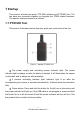
1 Startup This product includes two parts, PTS1000 software and PTS1000 tool. The two parts are connected together to complete the TPMS related functions. The specific startup process is as follows. 1.1 PTS1000 Tool This section illustrates external features, ports and connectors of the tool. Figure 1-1 Sample PTS1000 Tool 1 The power supply and activating sensor indicator light: The power indicator light is always on after the device is started.
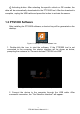
4 Activating button: After selecting the specific vehicle or OE number, the data will be automatically downloaded to the PTS1000 tool. After the download is complete, unplug the USB cable and press this button to activate the sensor. 1.2 PTS1000 Software After installing the PTS1000 software, a shortcut key will be generated on the desktop. Figure 1-2 Sample PTS1000 Software Icon 1. Double-click the icon to start the software.
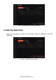
Figure 1- 4 Sample Vehicle Selection Interface 2 Vehicle Selection There are two ways to select the car model: "Manual Selection" and "OE Selection". Figure 2-1 Sample Manual Selection 10 PTS1000 User's Manual V1.
Figure 2-2 Sample OE Selection 1. Manual selection: select the corresponding vehicle by selecting the brand, model and year; 2. OE selection: select the corresponding vehicle by selecting the sensor brand and OE number; 3. It can switch to the corresponding sales area (the domestic version only has the Chinese area); 4. Reset can clear the selected vehicle information and re-select vehicle; 5. After selecting the vehicle, click the "enter" button to enter the function interface. 2.
Figure 2-3 Sample Manual Selection - Brand Selection Interface Figure 2-4 Sample Manual Selection - Model Selection Interface 12 PTS1000 User's Manual V1.
Figure 2-5 Sample Manual Car Selection Interface 2.2 OE Selection The OE selection interface is shown in below figures , and the vehicle selection is performed by selecting "sensor brand" and part number (OE number) at one time. Figure 2-6 Sample OE Selection Interface "OE number" is the abbreviation of the original sensor number, which is unique and almost all original sensors will print the OE number, sensor ID and other information on the sensor surface. 13 PTS1000 User's Manual V1.
Figure 2-7 Sample A Original Sensor Figure 2-8 Sample B Original Sensor 14 PTS1000 User's Manual V1.
Figure 2-9 Sample C Original Sensor Figure 2-10 Sample D Original Sensor 1. The position marked with 1 is the OE number of the sensor. The OE numbers of the four original sensors above are: PMV-C210, 13598773, QY2001A1, 25920615; 15 PTS1000 User's Manual V1.
2. The position marked with 2 is the ID information of the sensor. The ID numbers of the four original sensors above are: BAC6329 (hexadecimal), 589A4B90 (hexadecimal), 3A012426, 1656642260 (decimal); 3. The position marked 3 is the manufacturer of the sensor. It may also be on the back of sensor. 3 TPMS Function This function mainly include, TPMS sensor activation, TPMS sensor programming (only FOXWELL sensor programming) and sensor relearn guide.
Figure 3-2 prompts the customer to unplug the PTS1000 tool to activate the vehicle tire pressure sensor; Figure 3-2 Sample Unplug The PTS1000 Tool Figure 3-3 prompts the customer to activate the tire pressure sensor in the order of left front, right front, left rear, right rear, and spare tire (if any); Figure 3-3 Sample Active Sensors Figure 3-4 prompts the customer to switch to the desired tire. 17 PTS1000 User's Manual V1.
Figure 3-4 Sample Tire Position Selection Figure 3-5: When activating the sensor, you need to align the device antenna at the position of the valve sidewall and then press the activation button; Figure 3-5 Sample Activation Operation Interface Figure 3-6: After activating all tire sensors, connect the device to the computer, and click Read Activation Data to get the relevant information of the activated sensors. 18 PTS1000 User's Manual V1.
Figure 3-6 Sample Get The Activation Data Interface 3.1 Activation 3.1.1 Sensor Activation According to the guidance of the activation interface, unplug the device and activate the tire pressure sensor in the left front, right front, right rear, left rear, and spare tire (if any) in turn from the left front wheel. The corresponding indicator light of the selected tire will flash, and the power indicator light will flash when the activation is in progress.
The activation function can be used to diagnose the quality of the sensor, and the ID obtained by activation can be used for the "Clone ID by Activation" function in programming. 3.1.2 Favorites Click Favorites to add commonly used vehicles to Favorites. Next time when you select a car, you can directly enter Favorites to quickly select. Figure 3-8 Sample Favorites Interface 3.2 Programming There are three ways to program sensors, namely Manual create ID, Clone ID by Activation and Automatic create ID.
1. Keep the distance between the sensor to be programmed and the PTS1000 tool at 0~20cm; 2. The distance between other sensors and the PTS1000 tool should be kept more than 100cm; 3. The disassembled old sensor needs to be kept away from the vehicle. 3.2.1 Manual Create ID According to the original sensor format, it automatically defaults to decimal or hexadecimal. The format can also be modified as needed. The input box placeholder shows the length/digits of the ID.
Figure 3-12 Sample Manual Create ID-Scanning The Sensor Interface Figure 3-13 Sample Manual Create ID-Programming Interface 22 PTS1000 User's Manual V1.
Figure 3-14 Sample Manual Create ID-Programming Completed Interface 3.2.2 Clone ID by Activation The Clone ID by Activation interface is similar to manual create ID interface. You need to activate the vehicle sensor first, then connect the PTS1000 tool to the computer to obtain the activation data, and finally execute the activation clone function. The activation clone can only program one sensor at a time. Figure 3-15 Sample Clone ID by Activation-Programming Complete Interface 3.2.
Figure 3-16 Sample Automatic Create ID-The Interface To Detect Sensor Figure 3-17 Sample Automatic Create ID-Detected Sensors Interface Figure 3-18 Sample Automatic Create ID-Programming Completed Interface 3.3 Relearn Guide The relearn function provides the method of TPMS sensor learning and the related information of the original sensor, such as: supplier, frequency, part number, etc. There are two learning methods for this vehicle, namely clone sensor and self-learning.
Figure 3-19 Sample Relearn Guide Interface Figure 3-20 Sample Relearn Guide Expanding You can complete sensor replacement and matching by referring to the methods provided in the relearn guide. 4 My Account This section introduces user account registration and login. The customer can use the relevant functions of the product normally only after logging in first. After successful login, it will automatically jump to the TPMS function. 25 PTS1000 User's Manual V1.
Figure 4-1 Sample Login and Registration Interface Figure 4-2 Sample Login Success Interface 5 Activation It is necessary to activate and bind the product to the current user before the relevant functions of the product can be used normally. 26 PTS1000 User's Manual V1.
Figure 5-1 Sample Product Activation Interface 6 Setting It includes settings for Language, Sensor ID Format, Pressure Unit, Temperature Unit and About. Figure 6-1 Sample Setting Interface 6.1 Language The language flag is listed in the language setting option, select the corresponding flag, and select Yes in the confirmation interface to set the corresponding language. 27 PTS1000 User's Manual V1.
Figure 6-2 Sample Language Setting Interface Figure 6-3 Sample Language Setting Interface 6.2 Sensor ID Format In this selection, you can set the ID format to decimal or hexadecimal. Click the format you want to set, and select Yes in the confirmation interface. 28 PTS1000 User's Manual V1.
Figure 6-4 Sample Sensor ID Format Setting Figure 6-5 Sample Sensor ID Format Setting 6.3 Pressure Unit The pressure unit can be set according to the demand, and Kpa/Psi/Bar can be set respectively. 29 PTS1000 User's Manual V1.
Figure 6-6 Sample Pressure Unit Setting Figure 6-7 Sample Pressure Unit Setting 6.4 Temperature Unit The temperature unit can be set according to the demand, and the facility degree/Fahrenheit can be set respectively. 30 PTS1000 User's Manual V1.
Figure 6-8 Sample Temperature Unit Setting Figure 6-9 Sample Temperature Unit Setting 6.5 About Through this selection, you can view the corresponding software version. 31 PTS1000 User's Manual V1.
Figure 6-10 Sample About Interface 7 Update This function is mainly used to update product-related software such as APP, BOOT, firmware, vehicle software etc.. When have a new version, it will automatically jump to this interface after starting the software to guide customers to complete the upgrade function. Figure 6-11 Sample Update Interface 8 Help It is mainly used to provide user manual, basic function guide videos, tire pressure learning videos for special vehicles, etc.
Figure 6-12 Sample Help Interface FCC Statement Changes or modifications not expressly approved by the party responsible for compliance could void the user's authority to operate the equipment. This equipment has been tested and found to comply with the limits for a Class B digital device, pursuant to Part 15 of the FCC Rules. These limits are designed to provide reasonable protection against harmful interference in a residential installation.