
Technical data


Warning
ENGLISH
>
In order to install UTP-4RXA on flat surfaces or to walls,
assemble the provided brackets screwing them on the
bottom through the smaller holes (picture 6).
>
Fix UTP-4RXA on a flat surface or to wall (picture 7).
>
Please read the directions carefully before using the tool.
>
Do not connect this tool to any other device not specifically
described in this handbook.
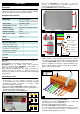
Technical data
Video input
Video output
Operating temperature
Power supply
Stand-by power
Maximum power
Dimensions (LxHxD)
Weight
Provided with
Receiver UTP-4RXA
Bracket for fixing to wall
Screws for fixing brackets
Spring female connector
Button for connector
Supplying cable
Instructions manual
CH1÷CH4 75 Ohm
UTP/FTP CAT5/6 - 600 m max
Nr 4 BNC 75 Ohm
-10 °C ÷ +40 °C
100÷240 Vac 50/60Hz IN/OUT
0,6 W
6
2,5 W
240x47x173 mm
1.080 g
1
2
4
1
1
1
1
7
A
B
C
D
E
F
G
H
30 mm
8
5 mm
A
-
blue
B
-
blue-white
C
-
green
D
-
green-white
E
-
brown
F
-
brown-white
G
-
orange
H
-
orange-white
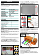
Utilities
UTP-4RXA is a 4 channels video signals receiver
conceived for CCTV systems distributed on twisted pair
cable and long distances.
UTP-4RXA receives the cameras video signal transmitted by
UTP-RXTX transmitter on CAT5 cable and provides it in
output on BNC connectors.
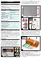
Every conductor couple of CAT5 cable corresponds to one
>
Remove the protecting sheath of CAT5 cable for about 30mm,
rip the conductors off for about 5mm and insert them one by
one inside the terminal board according to the colours
sequence on the label applied on UTP-4RXA bottom or as
shown in pictures 8 and 9.
>
Insert the conductors in the provided spring connector. In
order to open the contacts press the provided button or use a
screwdriver (picture 9).
channel video signal. The maximum transmission distance is
600m . It is also possible to adjust the gain of every channel.
Instructions
>
UTP-4RXA is set by factory in order to allow cameras
connections at a distance of up to 300m. In order to install one
or more than one camera at longer distances (up to 600m), it
is necessary to adjust the internal jumpers (picture 3).
>
Open the
UTP-4RXA
top unscrewing the 4 lateral screws.
>
Identify the jumper corresponding to the camera which has to
be installed at the distance of more than 300m (picture 4).
>
Adjust the jumper selecting the “600m” position (picture 5).
PRESS
WITH
A
SCREWDRIVER
A
B
C
D
E
PRESS
CH4 CH3
9
F
G
H
CH2
4
CH1
>
Insert the connectors arranged with CAT5 cable (picture 9) in
the male connectors on the UTP-4RXA back side.
>
Connect the video outputs CH1/CH4 to the DVR video input
by means of a BNC cable (picture 2).
>
Plug in the 230Vac supplying cable.
300m 600m
3 5
>
Switch the
UTP-4RXA
on pressing the button on the front.
>
If necessary, adjust the image coming from each camera by
means of the gain adjustment potentiometers positioned on
the back side.