ADMIRAL 36” Range Hood Hotte Installation Instructions Use and Care Guide Instructions d’installation Mode d’emploi et d’entretien FAD 367 W
INDEX WARNINGS AND REQUIREMENTS .....................................................................................................................................3 RECOMMENDATIONS AND SUGGESTIONS ......................................................................................................................6 DIMENSIONS and MAIN PARTS...........................................................................................................................................7 INSTALLATION ..............
READ AND SAVE THESE INSTRUCTIONS The Installer must leave these instructions with the homeowner. The homeowner must keep these instructions for future reference and for local electrical inspectors’ use. READ THESE INSTRUCTIONS BEFORE YOU START INSTALLING THIS RANGEHOOD WARNING: - TO REDUCE THE RISK OF A RANGE TOP GREASE FIRE: Never leave surface units unattended at high settings. Boilovers cause smoking and greasy spillovers that may ignite. Heat oils slowly on low or medium setting.
WARNING • • • • • • Venting system MUST terminate outside the home. DO NOT terminate the ductwork in an attic or other enclosed space. DO NOT use 4" laundry-type wall caps. Flexible-type ductwork is NOT recommended. DO NOT obstruct the flow of combustion and ventilation air. Failure to follow venting requirements may result in a fire. ELECTRICAL REQUIREMENTS A 120 volt, 60 Hz AC-only electrical supply is required on a separate 15 amp fused circuit. A timedelay fuse or circuit breaker is recommended.
WARNING - TO REDUCE THE RISK OF FIRE, ELECTRICAL SHOCK, OR INJURY TO PERSONS, OBSERVE THE FOLLOWING: Installation Work And Electrical Wiring Must Be Done By Qualified Person(s) In Accordance With All Applicable Codes And Standards, Including Fire-Rated Construction. Sufficient air is needed for proper combustion and exhausting of gases through the flue (chimney) of fuel burning equipment to prevent backdrafting.
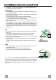
RECOMMENDATIONS AND SUGGESTIONS The Instructions for Use apply to several versions of this appliance. Accordingly, you may find descriptions of individual features that do not apply to your specific appliance. INSTALLATION • The manufacturer will not be held liable for any damages resulting from incorrect or improper installation. • Check that the main voltage corresponds to that indicated on the rating plate fixed to the inside of the hood.
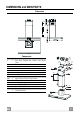
DIMENSIONS and MAIN PARTS Dimensions " " " " " " " " " " " " 15 Components Q.ty Product Components 1 Hood Body, complete with: Controls, Light, Blower, Filters 2 1 Telescopic Chimney comprising: 2.1 1 Upper Section 2.2 1 Lower Section 10 1 Damper 14.1 2 Air Outlet Connection Extension 15 1 Air Outlet Connection Ref. Q.ty Installation Components 7.2.1 2 Upper Chimney Section Fixing Brackets 7.
INSTALLATION Wall drilling and bracket fixing ÷1/16" 24" 12a 4"9/16 4"9/16 12"5/8 11 X 7.2.1 Wall marking: • Draw a vertical line on the supporting wall up to the ceiling, or as high as practical, at the center of the area in which the hood will be installed. • Draw a horizontal line at 24” above the hob. • Place bracket 7.2.1 on the wall as shown about 1/16” from the ceiling or upper limit aligning the center (notch) with the vertical reference line.
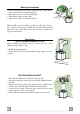
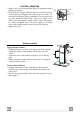
Mounting the hood body Vr • Before attaching the hood body, tighten the two screws Vr located on the hood body mounting points. • Hook the hood body onto the screws 12a. • Fully tighten support screws 12a. • Adjust screws Vr to level the hood body. 12a Note: The Hood body should be secured to wall studs. If necessary, install a wood support behind the dry wall, flush mounted between 2 studs. This will provide the necessary structure and support for mounting.
ELECTRICAL CONNECTION • Remove the cover from the Field Wiring Compartment with a phillips screwdriver. • Feed the Power Supply Cable through the electrical knockout. Connect the Power Supply Cable to the range- hood cable. Attach the Power Supply Cable grounding lead to the green screw provided. Attach the White lead of the power supply to the White lead of the rangehood with a twist-on type wire connector.
USE A B C D E F G H Control board Key B Function Display Switches the blower motor on and off at the Indicates the selected speed. latest selected speed Decreases the vent speed. C Increases the vent speed. D By pressing this key it is possible to activate HI appears. The spot down on the right side the intensive speed from any previously se- flashes once a second. lected speed. The intensive speed can be activated even when the motor is OFF. This speed has been timed at 10 minutes.
CARE REMOTE CONTROL (OPTIONAL) This range hood can be controlled by a multi-function remote control available through your local Franke Dealer. Metal grease filters Filters can be washed in the dishwasher. They need to be washed when FF-sign appears on the display or in any case every 2 months, or even more frequently in case of particularly intensive use of the hood. Alarm reset • Switch off the hood and the lights. If the 24h-function has been activated this has to be deactivated.
Charcoal filter (ductless version) • This filter cannot be washed or regenerated. It must be replaced when the EF appears on the display or at least once every 4 months. Activation of the alarm signal • In the recycling version hoods the filter saturation alarm must be activated during the installation or later. • Switch off the hood and the lights. • Disconnect the hood from the main voltage supply. • After restoring the connection press and hold B-key.
TABLE DES MATIÈRES AVERTISSEMENT ET CONDITIONS N ÉCESSAIRES ......................................................................................................15 CONSEILS ET SUGGESTIONS ..........................................................................................................................................18 DIMENSIONS et PRINCIPALES PIÈCES............................................................................................................................19 INSTALLATION ..........
LIRE ET CONSERVER CES INSTRUCTIONS L’installateur doit laisser ces instructions au propriétaire. Le propriétaire doit conserver ces instructions en vue d’une utilisation subséquente et pour le bénéfice de l’inspecteur en électricité.
AVERTISSEMENT • • • • • • Le système d’évacuation DOIT se terminer à l’extérieur. N’ÉVACUEZ PAS le conduit dans un grenier ou dans tout autre espace fermé. N’UTILISEZ PAS un clapet de sécheuse à 4 pouces. ON DÉCONSEILLE l’emploi de conduit d’évacuation flexible. N’ENCOMBREZ PAS la circulation d’air. Le fait de ne pas respecter ces avertissements pourrait occasionner un incendie.
AVERTISSEMENT – POUR MINIMISER LES RISQUES D’INCENDIE, CHOC ÉLECTRIQUES OU BLESSURES, OBSERVER CETTE RÈGLE : l’installation et le raccordement électrique ne doivent être effectués que par un technicien(s) qualifié, selon tous les codes municipaux. Afin d’obtenir un rendement maximal en ce qui a trait à la combustion ainsi qu’à l’évacuation des gaz par la conduite de cheminée et pour qu’il n’y ait pas de reflux des gaz de combustion, une bonne aération est nécessaire pour tous les appareils à combustion.
CONSEILS ET SUGGESTIONS Les instructions d’utilisation s’applique à plusieurs versions de ce type d’appareil. En conséquence, il est possible que vous trouviez des descriptions de caractéristiques ne s'appliquant pas à votre appareil. INSTALLATION • Le fabricant décline toute responsabilité en cas de dommage dû à une installation inadéquate ou non conforme aux règles de l’art. • Vérifiez que la tension du secteur correspond à la valeur qui figure sur la plaquette apposée à l’intérieur de la hotte.
DIMENSIONS et PRINCIPALES PIÈCES Dimensions " " " " " " " " " " " " 15 Composantes Ref. 1 2 2.1 2.2 10 14.1 15 Ref. 7.2.1 7.
INSTALLATION Perçage de la paroi et fixation des brides ÷1/16" 24" 12a 4"9/16 4"9/16 12"5/8 11 X 7.2.1 • Tracer sur la paroi une ligne verticale allant jusqu’au plafond ou à la limite supérieure, au centre de la zone prévue pour l’installation de la hotte. • Tracer une ligne horizontale à 24 pop. au-dessus du plan de cuisson. • Poser comme indiqué une bride 7.2.1 sur la paroi à 1/16 pop. du plafond ou de la limite supérieure, en alignant son centre (encoche) sur la ligne verticale de repère.
Montage du corps de la hotte Vr • Avant d’accrocher le corps de la hotte, serrer les deux vis Vr situées sur les points d’ancrage du corps de la hotte. • Accrocher le corps de la hotte solidement aux vis 12a prévues à cet effet. • Ajuster les vis Vr afin de placer le corps de la hotte à niveau. 12a Note: Le corps de la hotte devrait être fixer au poteau mural. Si nécessaire, installer un support en bois derrière la paroi sèche, à mi-chemin entre deux poteaux muraux.
BRANCHEMENT ÉLECTRIQUE • Retirer le couvercle du compartiment de filage à l’aide d’un tournevis Phillips. • Passer le câble d’alimentation dans la pastille enfonçable. Brancher le câble d’alimentation sur la hotte. Attacher le conducteur de mise à la terre du câble d’alimentation à la vis verte fournie. Attacher le fil blanc du câble d’alimentation au fil blanc de la hotte avec une cosse (connecteur de fils).
UTILISATION A B C D E F G H Tableaux des commandes Touche Fonction Afficheur Allume et éteint le moteur de ventilation à la A Affiche la vitesse sélectionnée. dernière vitesse utilisée Diminue la vitesse de ventilation. B C Augmente la vitesse de ventilation. D Active la vitesse intensive à partir de n’importe Affiche HI et le point en bas à droite clignote quelle vitesse, même du moteur arrêté. Cette une fois par seconde.
SOIN ET ENTRETIEN TÉLÉCOMMANDE (EN OPTION) Cet appareil peut être contrôlé à l’aide d’un télécommande alimentée par une pile alcaline carbone-zinc de type AAA (1.5 volt). Filtres à graisse métalliques Ils sont lavables au lave-vaisselle et doivent être lavés chaque fois que le symbole FF s’affiche ou environ tous les 2 mois, ou plus souvent même, en cas d’utilisation particulièrement intensive.
Filtre anti-odeur au charbon actif (version filtrante) • Il ne peut être ni lavé, ni récupéré. Il faut le changer quand EF s'affiche ou au moins tous les 4 mois. Déclenchement du signal d’alarme • Pour les hottes de la version filtrante, l’alarme indiquant la saturation des filtres doit être activée au moment de l’installation ou ultérieurement. • Éteindre les lumières et le moteur d’aspiration. • Débrancher la hotte du réseau électrique. • Rétablir le branchement, puis presser et maintenir la touche B.
436003936_01 - 070811